Microchip for analysis, analysis system having the same, and analysis method

a microchip and analysis system technology, applied in the field of microchip analysis, can solve the problems of inability to obtain a uniform flow, product cost, and inability to complete air extraction, and achieve the effects of reducing production cost, simple configuration, and simplifying connection operation

Inactive Publication Date: 2010-11-30
SEIKO INSTR INC
View PDF12 Cites 6 Cited by
  • Summary
  • Abstract
  • Description
  • Claims
  • Application Information

AI Technical Summary

Benefits of technology

[0015]Thus, it is an object of the invention to provide a microchip for analysis which has a morphology of a microchip with a miniaturized substrate, which requires low production cost due to facilitated preparation or assembling, which is disposable, making it easy to use, and which eliminates a risk of contamination in flow channels, an analysis system having the microchip for analysis, and an analysis method using the same.

Problems solved by technology

In addition, there may be stagnation in the flow of a fluid around a corner portion 105a. Thus, it is impossible to obtain a uniform flow and there is possibility that a complete extraction of air is not achieved, with residual air still remaining.
Thus, in consideration of the complexity of the operation and the increase in the product cost, it has been difficult in practice to replace the substrate 100 with a disposable one.
In that case, even though the flow channels or the pumps are cleaned with a cleaning solution, there still is a risk that the analyte in the sample solution of the previous analysis remains somehow in the flow channels or the pumps to possibly react with the sample solution for the subsequent analysis, thereby lowering reliability of analysis.
Further, in the case of supplying the sample solution to the reaction bath section 105 by purging with the buffer solution, there is a risk that both solutions may diffuse into each other at an interface, thus making the point of completion of the reaction unclear, or making the concentration of the sample solution inaccurate, to impair reliability of the analysis result.
In addition, it is difficult in practice to use and discard the substrate 100 and the substrate 100 should be used repeatedly in a number of analyses.

Method used


Image

  • Microchip for analysis, analysis system having the same, and analysis method
  • Microchip for analysis, analysis system having the same, and analysis method
  • Microchip for analysis, analysis system having the same, and analysis method

Examples


first embodiment

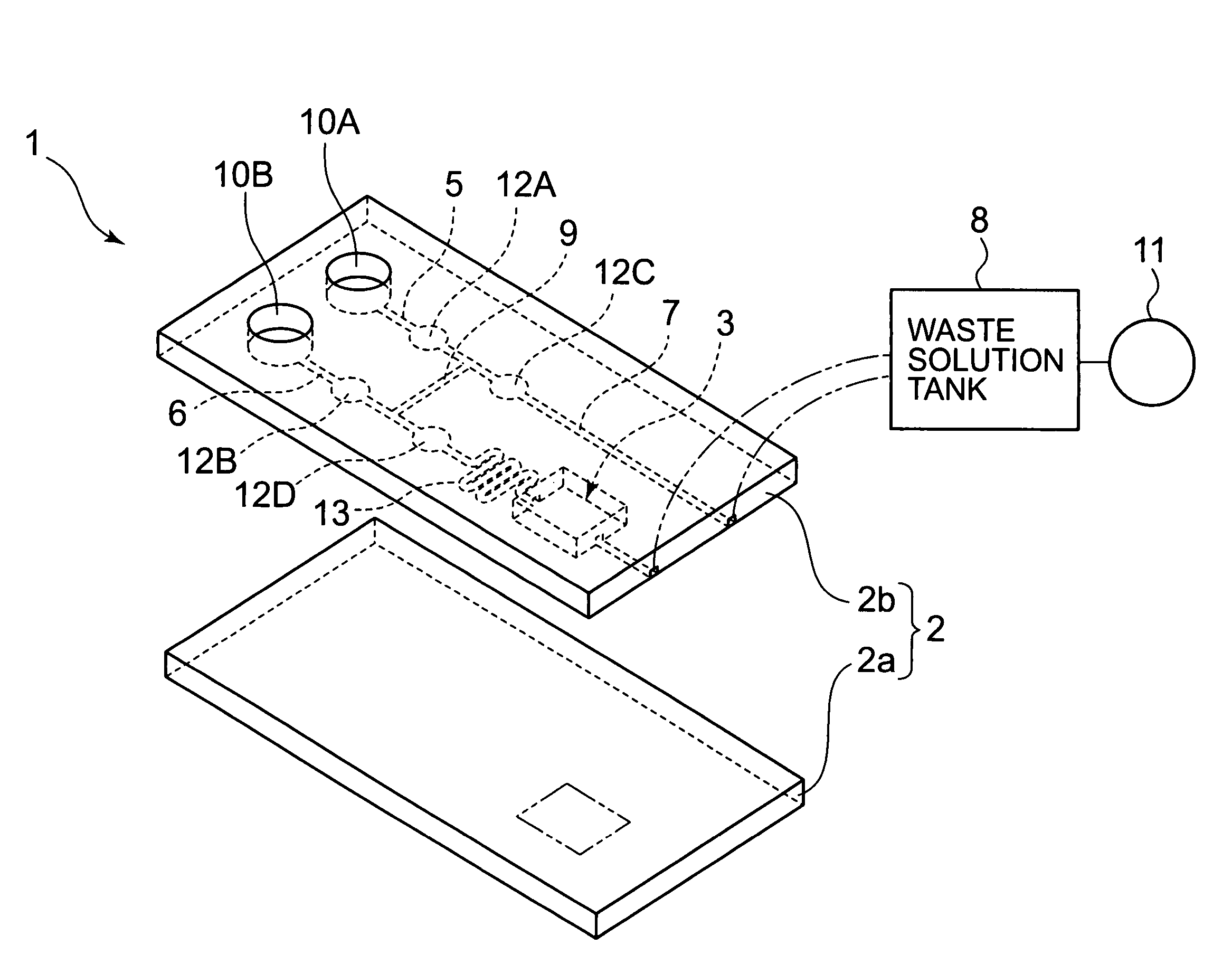
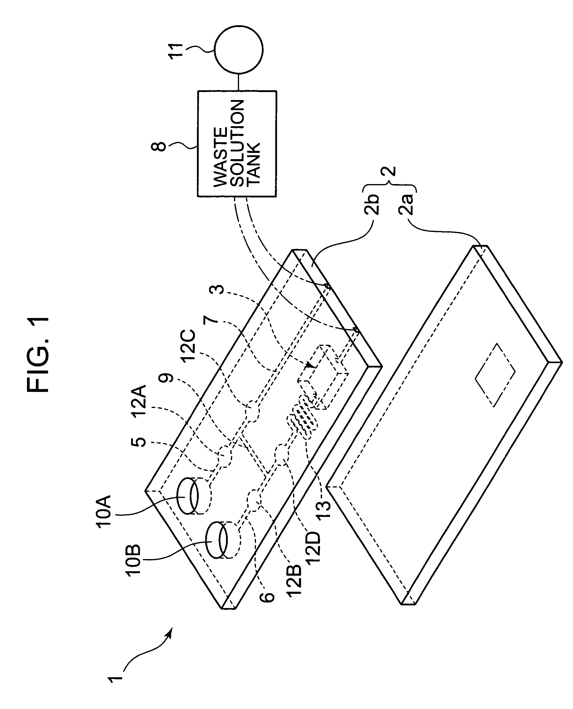
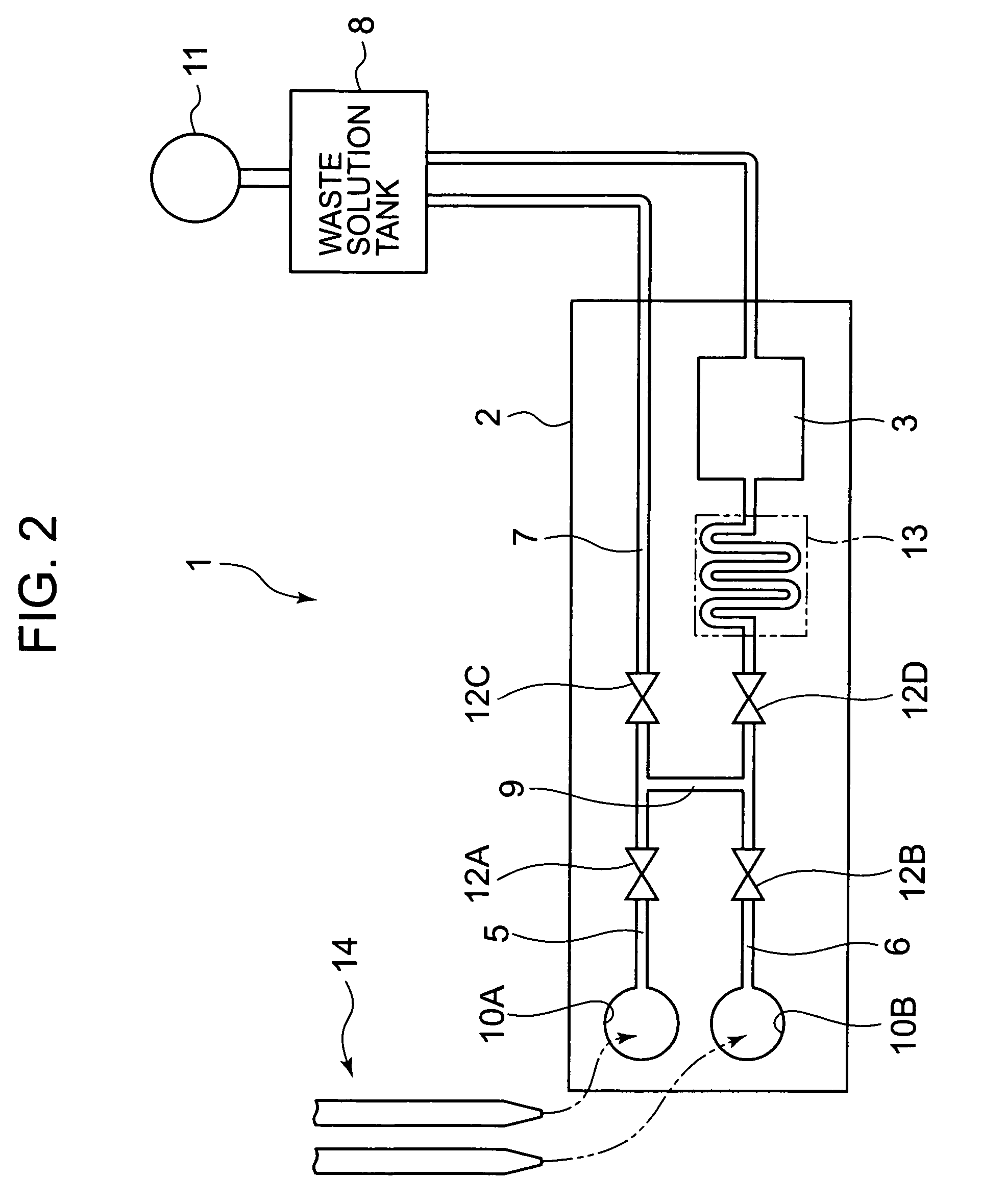
[0059]FIG. 1 is an exploded perspective view of a microchip for analysis 1 of the invention, and FIG. 2 is a schematic plan view of the microchip for analysis 1 of the invention. The microchip for analysis 1 of the invention is to analyze interactions of biomolecules such as protein, and in particular, to detect the state of binding reaction (for example, binding strength, binding rate, dissociation constant, and the like) between a ligand and an analyte.

[0060]The microchip for analysis 1 is provided with, on a minute substrate 2 having two plate members 2a and 2b laminated one on other, a reaction bath section 3 where a reaction is performed by mainly forming a concave portion in one plate member 2b by using photolithography or the like, a sample solution supply channel 5 which supplies a sample solution for analysis, a buffer solution supply channel 6 which supplies a buffer solution having functions of cleaning flow channels or of buffering (function of dissociation), and a waste...

second embodiment

[0098]Next, a microchip for analysis 40 of a second embodiment of the invention shown in FIG. 10 will be described. The same elements as those of the microchip for analysis 1 of the first embodiment shown in FIGS. 1 and 2 are represented by the same reference numerals and thus the descriptions thereof will be omitted.

[0099]The microchip for analysis 40 shown in FIG. 10 has a configuration which is substantially identical to the four-flow channel-configuration of the microchip for analysis 1 shown in FIGS. 1 and 2. That is, in addition to the configuration of the microchip for analysis 1 shown in FIGS. 1 and 2, a buffer solution supply channel 6′ (another buffer solution supply channel) and the reaction bath section 3 are connected to form a third flow channel, the ligand solution supply channel (treatment solution supply channel) 5′ and the waste solution channel 7′ are connected to form a fourth flow channel. Further, a connecting channel (connecting channel for treatment solution)...

third embodiment

[0104]Next, a microchip for analysis 41 of a third embodiment of the invention shown in FIGS. 11 and 12 and the analysis system will be described. The same elements as those of the microchip for analysis 1 or 40 of the first or second embodiment are represented by the same reference numerals, and the descriptions thereof will be omitted.

[0105]The above-described microchip for analysis 40 of the second embodiment is such that the analysis of the sample solution is prepared by allowing the ligand solution or the treatment solution for pre-treatment solution (SAM reagent and blocking reagent) to flow in the reaction bath section 3 through each flow channel in the microchip for analysis 40. However, the microchip for analysis 40 is disadvantageous in that the configuration has defects since there are 8 flow channels, and the flow channels for the buffer solution (the first, third, fifth, and seventh flow channels) overlap one another, which results in causing the microchip for analysis ...


PUM

PropertyMeasurementUnit
flow rateaaaaaaaaaa
sizeaaaaaaaaaa
speedaaaaaaaaaa

Abstract

A microchip has a substrate on which there are formed a reaction bath section, a first flow channel to which are connected a supply channel that supplies a buffer solution and the reaction bath section, a second flow channel to which are connected a supply channel that supplies a sample solution containing a first substance and a channel that discharges the sample and buffer solutions to an exterior of the substrate, and a connecting channel connecting the first flow channel to the second flow channel. The reaction bath section receives the first and second substances so that the first and second substances react in the reaction bath section. The first and second flow channels are provided with valves disposed relative to the connecting channel such that selective opening and closing of the valves causes the buffer solution to flow first into the reaction bath section at a preselected speed and the sample solution to flow second into the reaction bath section at the preselected speed to cause the first and second substances to react in the reaction bath section.

Description

BACKGROUND OF THE INVENTION[0001]1. Field of the Invention[0002]The present invention relates to a microchip for analysis which is used for an analysis of biomolecular interactions or the like, an analysis system having the same, and an analysis method.[0003]2. Description of the Related Art[0004]Conventionally, in order to analyze a biomolecular interaction such as protein or the like, an analysis method in which, for example, an analyte is bound to a ligand and the state of binding reaction (for example, binding strength, binding rate, etc.) is detected using a phenomenon of surface plasmon resonance (SPR) is known. In particular, analysis apparatuses as described in Non-Patent Documents 1 and 2 have been widely used.[0005]An example of such an analysis method will be described in summary. A ligand is preliminarily modified on a base layer (metal film) of a reaction bath section, a sample solution containing an analyte is supplied to the reaction bath section with a predetermined ...

Claims


Application Information

Patent Timeline
Patent Type & Authority Patents(United States)
IPC IPC(8): G01N15/06B01L99/00F01N3/28G05D7/00G01N1/00B01L3/00B01L9/00G01N33/543G01N35/00G01N35/08G01N37/00
CPCB01L3/5027B82Y30/00B01L3/502715B01L9/527B01L2200/0684B01L2200/10B01L2200/141B01L2300/0816B01L2300/1805B01L2400/0487B01L2400/0655
Inventor YAMAMOTO, MINAOSHINOGI, MASATAKA
Owner SEIKO INSTR INC
Why Eureka
Try Eureka