
Sagnac effect based radio frequency electronic gyroscope incorporated in CMOS integrated circuit

a radio frequency electronic and gyroscope technology, applied in the field of gyroscopy, can solve problems such as phase difference between the two

Active Publication Date: 2015-12-15
TAL NIR +2
View PDF20 Cites 7 Cited by
  • Summary
  • Abstract
  • Description
  • Claims
  • Application Information

AI Technical Summary

Benefits of technology

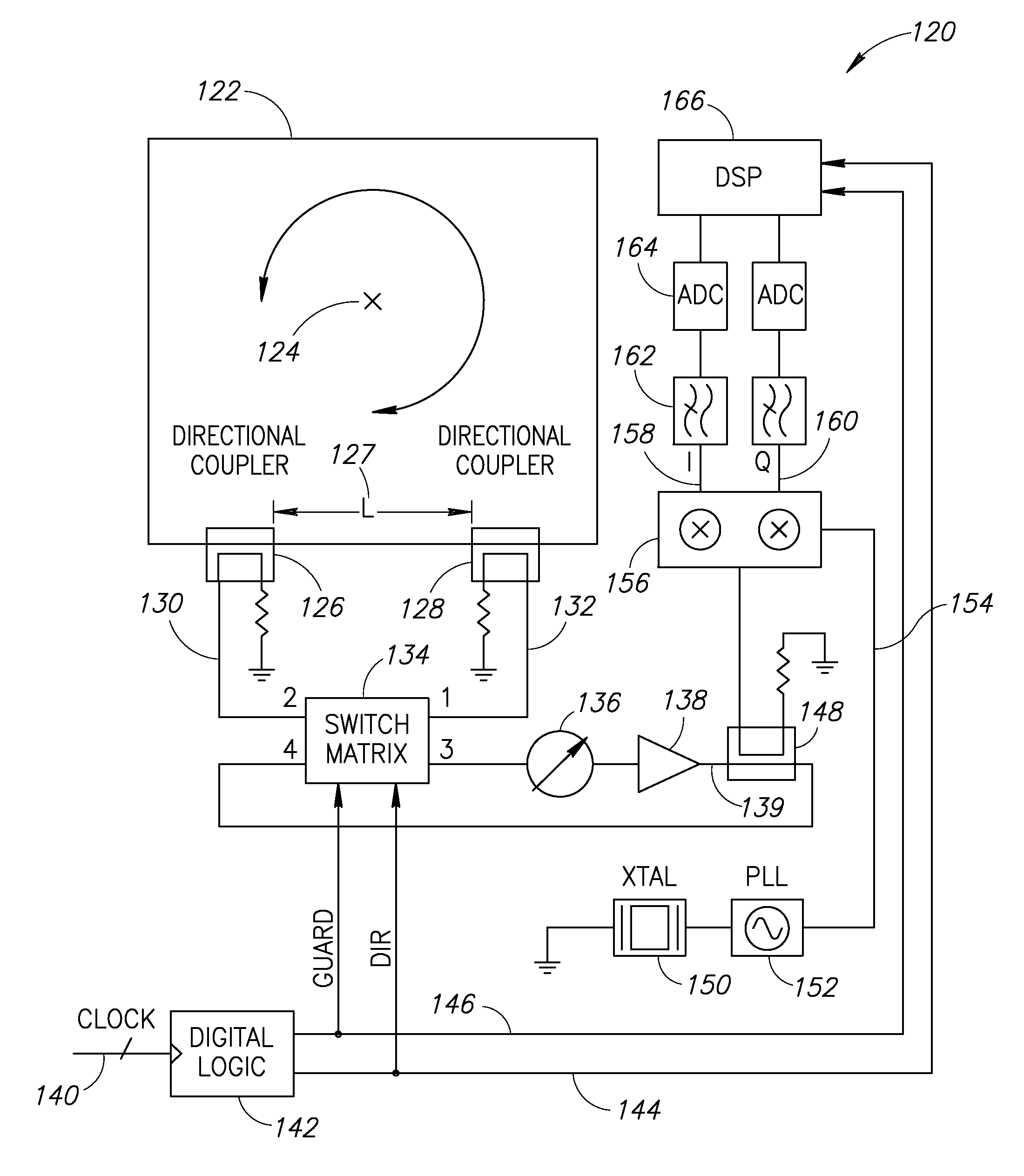
The present invention is about a new and useful structure for an electronic gyroscope that can be made in a low-cost process. It detects and measures movement by using the Sagnac effect in radio-frequency signals that propagate in two opposite directions in a loop that undergoes rotation. The invention eliminates the need for mechanical moving parts, which are used in MEMS-based gyroscopes and require a special fabrication process. The apparatus and method of the invention can be integrated into a standard low-cost CMOS fabrication process and can be integrated with other functions on the same IC. The invention also uses a shared oscillator, amplifier, and detector and a controller to alternate between the two directions of propagation and to introduce a guard band to eliminate possible overlap between the two directions, resulting in a more accurate estimate of the phase shifts.

Problems solved by technology

This will result in a phase difference between the two from which the rotational movement may be extracted by means of signal processing.

Method used


Image

  • Sagnac effect based radio frequency electronic gyroscope incorporated in CMOS integrated circuit
  • Sagnac effect based radio frequency electronic gyroscope incorporated in CMOS integrated circuit
  • Sagnac effect based radio frequency electronic gyroscope incorporated in CMOS integrated circuit

Examples


first embodiment

[0095]A time domain voltage waveform plot of the system operating in accordance with the method of the present invention where it operates in discontinuous phase mode without a guard interval is shown in FIG. 10. Trace 250 shows the voltage of the RF signal propagating in the CW direction, while trace 252 shows the waveform of the RF signal propagating in the CCW direction. Trace 260 shows the DIR signal controlling the system to alternate between CW and CCW directions using the switch matrix in the system, as was explained supra. As can be seen in the figure, the instances for which direction reversal is triggered are 254, 256, 258, etc., spaced apart by ΔT. This duration is chosen long enough such that when the system is amplifying the RF signal in the CW direction (e.g., between time stamps 254 and 256), the CCW direction voltage decays completely. When the system is amplifying the RF signal in the CCW direction (e.g., between time stamps 256 and 258), the voltage in the CW direc...

second embodiment

[0096]A time domain voltage waveform plot of the system operating in accordance with the method of the present invention where it operates in continuous phase mode without a guard interval is shown in FIG. 11. Trace 270 shows the voltage of the RF signal propagating in the CW direction, while trace 272 shows the waveform in the CCW direction. Trace 280 depicts the DIR signal controlling the system to alternate between CW and CCW directions. As can be seen the figure, the instances for which direction reversal is triggered are 274, 276, 278, etc., spaced by ΔT each. This duration is chosen short enough such that when the system is amplifying in the CW direction (e.g., between time stamps 274 and 276 the signal propagating in the CCW direction does not completely decay before being amplified again at timestamp 276. When the system is amplifying the signal propagating in the CCW direction (e.g., between time stamps 276 and 278), the signal propagating in the CW direction does not compl...

third embodiment

[0097]A time domain voltage waveform plot of the system operating in accordance with the method of the present invention where it operates in discontinuous phase mode with a guard interval is shown in FIG. 12. Trace 290 shows the time domain voltage waveform of the RF signal propagating in the CW direction, whereas trace 292 shows the time domain voltage waveform of the RF signal propagating in the CCW direction. Trace 312 shows the DIR control signal, which is used to alternate between amplification in the CW and CCW directions, as explained supra. Trace 314 shows the GUARD control signal, which serves to interrupt the operation of the loop at twice the frequency of the DIR signal. For example, between time stamps 296 and 298 the GUARD signal is LOW, allowing for the RF signal to propagate in the loop. The direction control signal DIR is set to HIGH for this interval and hence trace 290 shows the CW waveform building up and oscillating at full span. In contrast, between time stamps...


PUM


Abstract

A radio frequency based electronic gyroscope function that may be incorporated in its entirety on a monolithic integrated circuit (IC). The detection and measurement of movement in a particular plane is based on the Sagnac effect as it applies to a radio frequency signal that propagates in two different directions in a loop that may be subject to rotational perturbation. In one embodiment, three mutually perpendicular loops that are incorporated into the same integrated circuit and are used to detect and measure movement in three planes (roll, pitch and yaw) thereby allowing a signal processing unit to quantify a general three dimensional movement. The gyroscope can be incorporated into an IC that is used in portable device, such as a mobile handset, to provide it with inertial navigation and movement detection and measurement capabilities.

Description

REFERENCE TO PRIORITY APPLICATION[0001]This application claims priority to U.S. Provisional Application Ser. No. 61 / 881,477, filed Sep. 24, 2013, entitled “A Novel Sagnac Effect RF based Gyroscope in CMOS,” incorporated herein by reference in its entirety.FIELD OF THE INVENTION[0002]The present invention relates to the field of gyroscopy and more particularly relates to the field of electronically realized gyroscopes based on the Sagnac effect, wherein rotational movement of a loop is quantified based on the difference between the propagation paths for radio-frequency signals that are propagating in it in the two opposite directions.BACKGROUND OF THE INVENTION[0003]Gyroscopes are sensors that can sense rotational speed of the measurement frame with respect to an inertial one. In recent years, they have become ubiquitous in mobile devices (smart phones, tablets, etc.) while supporting applications such as gaming, augmented reality and optical image stabilization (OIS). A vibrating st...

Claims


Application Information

Patent Timeline
Patent Type & Authority Patents(United States)
IPC IPC(8): G01C19/64G01P3/44G01C19/72
CPCG01C19/64G01P3/44G01C19/727G01C19/722
Inventor TAL, NIRWOLBERG, DANBARRY, DARYL WADE
Owner TAL NIR
Learn More