Apparatus and method for dispensing a hyperpolarized fluid

a technology of contrast agent and fluid, applied in the direction of magnetic variable regulation, instruments, measurement using nmr, etc., can solve the problems of limited application to endoscopic, invasive and interventional applications, and achieve the effect of avoiding the effects of spatial inhomogeneity, reducing limitations, and being easy to achiev

Inactive Publication Date: 2015-12-29
KONINKLIJKE PHILIPS ELECTRONICS NV
View PDF22 Cites 0 Cited by
  • Summary
  • Abstract
  • Description
  • Claims
  • Application Information

AI Technical Summary

Benefits of technology

[0020]A further advantage of the present invention is that the hyperpolarisation process on the basis of OAM photonic beam, notably when applied to a 13C compound is hardly sensitive to the specific labelling position of the 13C nucleus in the 13C compound. Accordingly, this aspect of the invention relieves limitations on the specific compounds that can be hyperpolarised. That is, the present invention does not pose restrictions on particular metabolically relevant compounds that can be labelled with a 13C hyperpolarised nucleus. Examples of such metabolically relevant compounds are glucose, pyruvate, bicarbonate, lactate, glutamine, choline etc. Additionally, drugs or artificial blood substances like perfluoro carbons and PFOB (perfluorooctyl bromide) can be hyperpolarised prior to injection. Hence, the present invention enables the examination by way of hyperpolarised enhanced contrast magnetic resonance imaging of a wide variety of metabolic and physiological processes.
[0021]The invention also pertains to a magnetic resonance examination system that is provided with a dispenser of the invention. According to a related aspect, the magnetic resonance examination system and the dispenser are provided with a synchroniser control to synchronise the operation of the RF system 901 (see FIG. 1) and gradient system 902 (see FIG. 1) of the magnetic resonance examination system with the operation of the RF-polariser subsystem 4 (see FIG. 1) of the dispenser. The synchronisation is arranged so that the RF (B1) field of the polariser unit is activated to excite the hyperpolarised recipient nuclei in the dispensing unit when there is no disturbing RF and gradient magnetic field pulse of the magnetic resonance examination system. Alternatively, a RF and / or gradient screen 904 (see FIG. 1) e.g. of aluminum or copper can be provided to shield the hyperpolarised secondary nuclei from the RF and / or gradient magnetic fields of the magnetic resonance examination system.
[0022]In a further aspect of the invention a magnetic field is applied in the dispenser. Notably, in this aspect of the invention the transfer path passes through this magnetic field from the chamber in which the OM photonic beam and the (optional) polarisation transfer system in which the hyperpolarisation is transferred from the source-compound to the recipient-compound. This direction of the magnetic field is a preferred direction of the polarisation generated by the OAM photonic beam. This is achieved for example when the dispenser is located in the fringe field of the main magnet 903 (see FIG. 1) of the magnetic resonance examination system. Notably, a magnetic field of 0.2 T to 0.5 T or even 1.0 T maintains the generated polarisation and is easy to achieve in a magnetic resonance examination system. These field strengths are available in the fringe field of the main magnet 903 as illustrated in the example of FIG. 2. The magnetic field in the dispenser maintains the hyperpolarisation is maintained when the hyperpolarised compound is transferred out of the OAM photonic beam. For the embodiment where NMR pulse sequences are employed to transfer spin polarisation from high gyromagnetic ratio spins to low gyromagnetic ratio spins, the use of small volumes is advantageous to avoid effects of spatial inhomogeneity of the magnetic field in the NMR polarisation transfer sequence. In practice, the OAM photonic beam for example has an incident spot of 20-50 μm and up to 1000 spots may be used in parallel to achieve polarisation at a distinct location in a gross volume of about 10 cc. In such a small volume spatial inhomogeneities of the magnetic field are not relevant and the fringe field of the main magnet 903 can be used for NMR polarisation transfer after OAM hyperpolarisation. Alternatively, the dispenser is provided with its own magnet system which generates the magnetic field in the chamber.
[0023]In a further application of the invention, water is hyperpolarised by the OAM photonic beam at appropriate optical wavelengths, e.g. in the far-red spectrum, and administered, e.g. injected or infused as a bolus. Detection of an arterial input function, and quantification of T1, allows for quantification of perfusion in tissue. Multiple bolus injections can be used to improve SNR, since the water signal decays with T1 or can be crushed by MRI pulse sequences. The technique can easily be combined with DCE-MRI (after injection of the hyperpolarized water), and thus combined perfusion and permeability maps can be obtained.
[0024]An injector is used for intravenous administration of isotonic saline solutions, which are hyperpolarised on the basis of OAM polarization. A volume flow rate of 10 ml / s at reasonable degrees of polarization (>20%) can readily be achieved. A first implementation includes: dynamic scan acquisition of the region of interest, either 2D or 3D, monitors passage of the hyperpolarized water bolus; use low flip angle 3D gradient echo sequence to prevent rapid decay of the magnetization; combination with profile sharing techniques like keyhole and VIPR, and reconstruction using Compressed Sensing to allow for high resolution 4D images. The reference image(s) can be obtained in two modes: multiple water boluses and acquisition timed relative to injection to ensure equal signal levels, or semi-steady state injection of polarized water.
[0025]An additional application of this method allows for input function quantification: Use time stamping for injector and imaging device to get accurate information on time of arrival, and bolus dispersion.

Problems solved by technology

Hence, these known applications are limited to endoscopic, invasive and interventional applications.

Method used


Image

  • Apparatus and method for dispensing a hyperpolarized fluid
  • Apparatus and method for dispensing a hyperpolarized fluid
  • Apparatus and method for dispensing a hyperpolarized fluid

Examples


Embodiment Construction

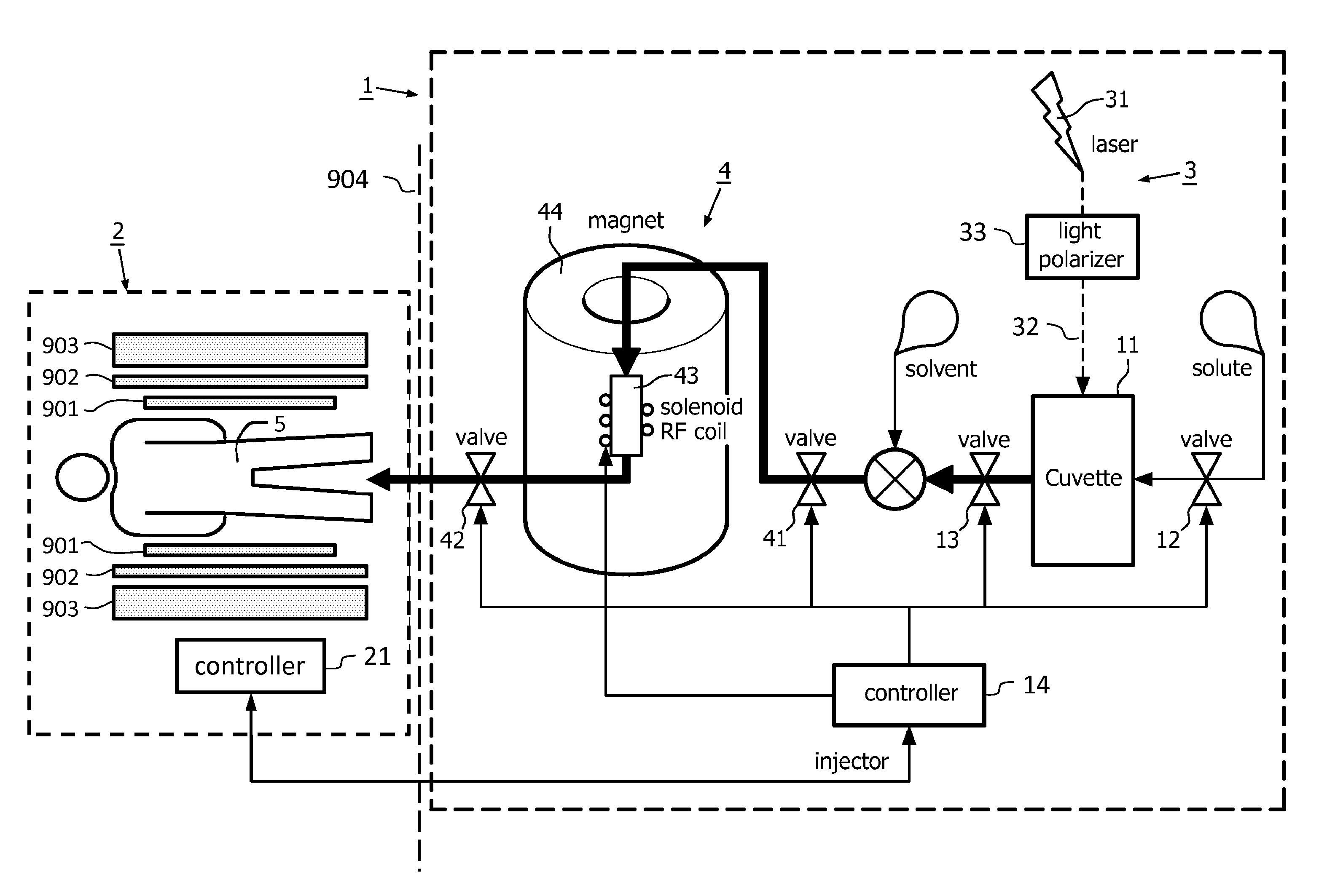
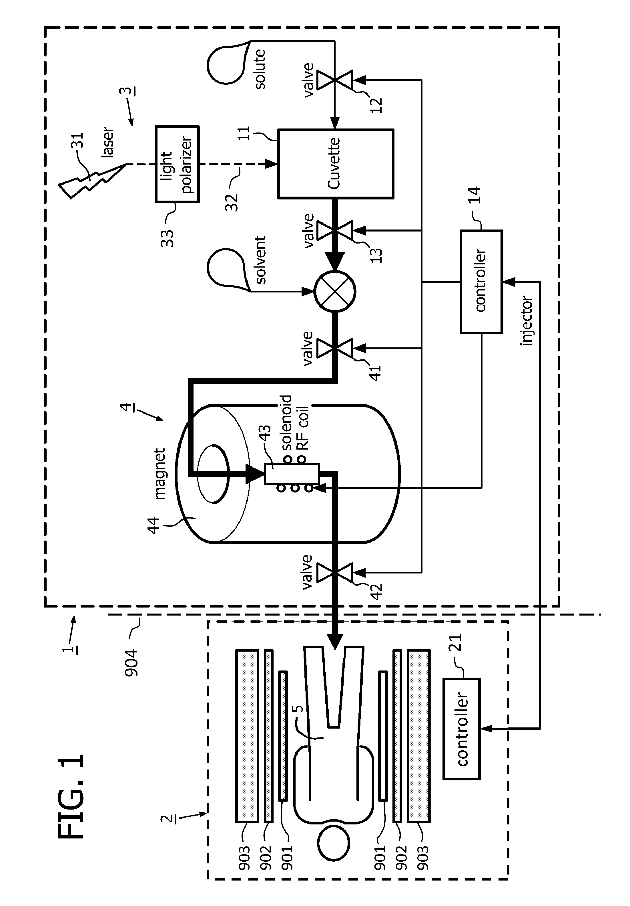
[0035]FIG. 1 shows a schematic representation of a dispenser 1 of the invention in co-operation with a magnetic resonance examination system 2. The chamber 11 of the dispenser 1 is formed as a cuvette 11. The photonic hyperpolarisation system 3 includes a laser 31 and a light polariser 33 which forms the OAM photonic beam 32 that is endowed with orbital angular momentum. This OAM photonic beam is directed into the cuvette 11 which contains the source-compound in the form of the solute, so that in the cuvette the hyperpolarised source-compound is formed. This hyperpolarised source-compound is then fed to the polariser transfer system 4. In the polariser transfer system 4, the hyperpolarisation of the solute source-compound is transferred, e.g. by nuclear polarisation transfer, to the recipient-compound that is added as a solute to the solvent. The hyperpolarised solution with the hyperpolarised solute recipient-compound is then applied to a dispensing unit (not shown) to be administe...


PUM


Abstract

A dispenser is provided for producing a nuclear hyperpolarized contrast agent. The dispenser comprises a chamber to receive a compound. A photonic hyperpolarization system generates an OAM-photonic beam endowed with orbital angular momentum and is arranged to direct the OAM-photonic beam into the chamber so as to generate nuclear hyperpolarization in the compound. The chamber has an output over which the hyperpolarized compound can be issued. Since the hyperpolarization is generated ex-vivo, the penetration depth of the OAM-photonic beam in biological tissue is irrelevant for the present invention.

Description

CROSS-REFERENCE TO RELATED APPLICATIONS[0001]This application is a national stage application under 35 U.S.C. §371 of International Application No. PCT / IB2011 / 050480 filed on Feb. 4, 2011 and published in the English language on Aug. 25, 2011 as International Publication No. WO / 2011 / 101765, which claims priority to European Application No. 10153668.8 filed on Feb. 16, 2010, the entire disclosures of which are incorporated herein by reference.FIELD OF THE INVENTION[0002]The invention pertains generation of a hyperpolarised contrast agent. An optical system produces an OAM light-beam endowed with optical angular momentum. This OAM photonic beam generates nuclear hyperpolarisation in a compound which then can be employed as the hyperpolarised contrast agent in an MR examination.BACKGROUND OF THE INVENTION[0003]Such a photonic-based hyperpolarisation system is known from the international application WO2009 / 081360.[0004]The known photonic-based hyperpolarisation system includes a surfac...

Claims


Application Information

Patent Timeline
Patent Type & Authority Patents(United States)
IPC IPC(8): G01R33/28G01R33/56
CPCG01R33/281G01R33/282G01R33/5601
Inventor VAN DEN BRINK, JOHAN SAMUEL
Owner KONINKLIJKE PHILIPS ELECTRONICS NV
Why Eureka
Try Eureka