Method of setting flying height and flying height setting device

a technology of magnetic recording head and setting device, which is applied in the direction of magnetic recording, data recording, instruments, etc., can solve the problems of difficult to precisely detect touch down relative to the magnetic recording medium of damage to the thermally-assisted magnetic recording head and the magnetic recording medium,

Active Publication Date: 2016-01-05
TDK CORPARATION
View PDF17 Cites 2 Cited by
  • Summary
  • Abstract
  • Description
  • Claims
  • Application Information

AI Technical Summary

Benefits of technology

[0013]The vicinity of a medium opposed surface is heated by near-field light that is irradiated from the near-field light generating portion of the thermally-assisted magnetic recording head to a magnetic recording medium, and the medium opposed surface protrudes toward the magnetic recording medium side. It has become ascertained according to keen study by the inventors that the spot diameter of the near-field light may become smaller responding to demand of high recording density in recent years, and that the protrusion shape of the medium opposed surface attributable to heat in association with generation of the near-field light becomes precipitous. If the protrusion shape of the medium opposed surface of the thermally-assisted magnetic recording head is precipitous, the contact area with the magnetic recording medium in the thermally-assisted magnetic recording head becomes extremely small, so it may become difficult to precisely detect touch down relative to the magnetic recording medium of the thermally-assisted magnetic recording head can occur. If it becomes difficult to detect touch down, as a result of pushing the thermally-assisted magnetic recording head into the magnetic recording medium so as to make touch down detectable, the thermally-assisted magnetic recording head and the magnetic recording medium may be damaged. In the invention (Invention 1), touch down relative to the magnetic recording medium of the thermally-assisted magnetic recording head can be assuredly detected by touching down the thermally-assisted magnetic recording head while near-field light is generated by a drive current for setting the flying height, which is smaller than the drive current supplied to the light source to be a source for generating the near-field light. Therefore, optimum heater power that is supplied to the heater part and optimum drive current supplied to the light source in order to accomplish target flying height can be determined without causing damage to the magnetic recording medium and the thermally-assisted magnetic recording head. As a result, the flying height of the thermally-assisted magnetic recording head can be set to the target flying height.

Problems solved by technology

If the protrusion shape of the medium opposed surface of the thermally-assisted magnetic recording head is precipitous, the contact area with the magnetic recording medium in the thermally-assisted magnetic recording head becomes extremely small, so it may become difficult to precisely detect touch down relative to the magnetic recording medium of the thermally-assisted magnetic recording head can occur.
If it becomes difficult to detect touch down, as a result of pushing the thermally-assisted magnetic recording head into the magnetic recording medium so as to make touch down detectable, the thermally-assisted magnetic recording head and the magnetic recording medium may be damaged.

Method used


Image

  • Method of setting flying height and flying height setting device
  • Method of setting flying height and flying height setting device
  • Method of setting flying height and flying height setting device

Examples


example 1

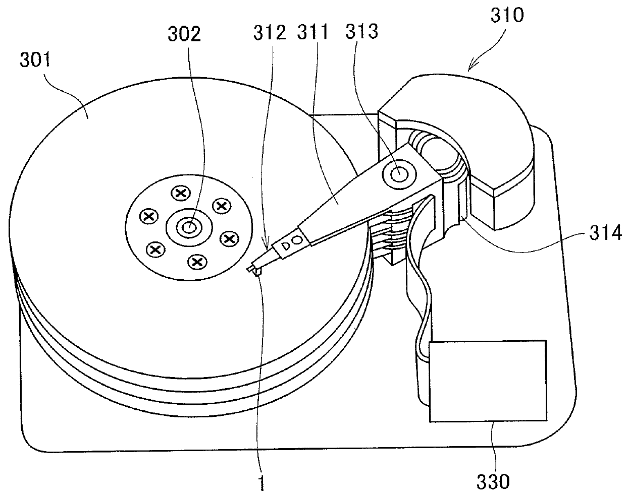
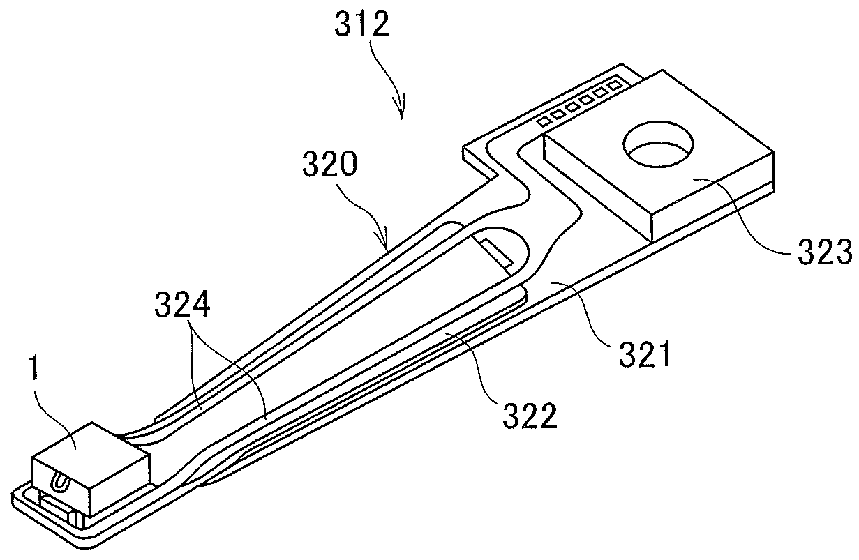
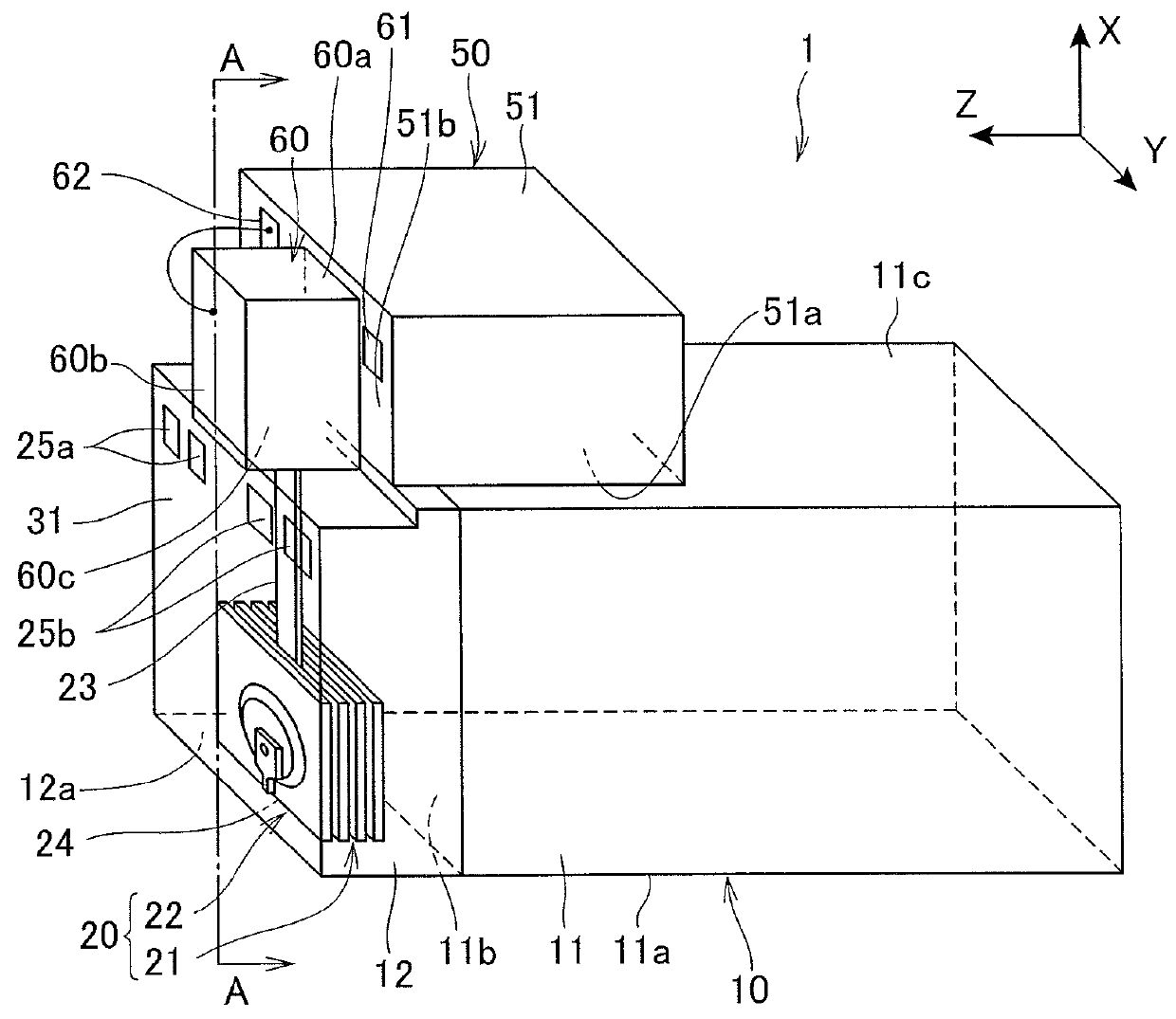
[0132]The thermally-assisted magnetic disk device having a configuration shown in FIGS. 1 to 6 was prepared, and the tentative optimum drive current LDI0 of the laser diode 60 in the thermally-assisted magnetic recording head 1 was determined. The tentative optimum drive current LDI0 was determined to 35 mA, which would be greater than a threshold current Ith (=15.5 mA) to start the laser oscillation in the laser diode 60.

[0133]Then, based on the formulae below, the 1st to 3rd drive currents for flying height setting LDI1 to LDI3, which would be 50%, 60% and 70% of the tentative optimum drive current LDI0, were calculated and set.

LDI1=(LDI0−Ith)×0.5+Ith=25.25 mA

LDI2=(LDI0−Ith)×0.6+Ith=27.20 mA

LDI3=(LDI0−Ith)×0.7+Ith=29.15 mA

[0134]The 1st to 3rd drive currents for flying height setting LDI1 to LDI3 were supplied to the laser diode 60, respectively; the heater power HTP was supplied to the heater part HT, a write current IW (=65 mA) was supplied to the writing coil 22e, and while the ...

experimental example 1

Measurement of Protrusion Shape Profile of Medium Opposed Surface (Head Part End Surface) in Thermally-Assisted Magnetic Recording Head

[0140]For the protrusion shape of the head part end surface 12a in the thermally-assisted magnetic recording head 1 in Example 1, a simulation analysis experiment was conducted.

[0141]This simulation analysis experiment was conducted using a finite element method.

[0142]In the present experimental example, a model where the waveguide 23 in the thermally-assisted magnetic recording head 1, the dielectric layer 32f contacting the side surface 23c of the waveguide 23 and the plasmon-generator 24 were made from TaOx, SiOx and Au, respectively, was adopted.

[0143]Further, in the model, width of the magnetic pole 22f in the track width direction (Y-axis direction), width of the waveguide 23 in the track width direction (Y-axis direction), height of the magnetic pole 22f in the Z-axis direction and height of the waveguide 23 in the Z-axis direction were set to...


PUM

PropertyMeasurementUnit
heightaaaaaaaaaa
thicknessaaaaaaaaaa
thicknessaaaaaaaaaa

Abstract

While a plurality of drive currents for flying height setting with current values smaller than a tentative optimum drive current are supplied to a light source, respectively, heater power is supplied to a heater part, and touch down of a thermally-assisted magnetic recording head is detected. Tentative optimum heater power is determined based on a correlation between the heater power when the touch down is detected and each drive current for flying height setting. The tentative optimum drive current is supplied to the light source part; the tentative optimum heater power is supplied to the heater part; a reference signal is recorded in a magnetic recording medium; and flying height of the thermally-assisted magnetic recording head is set by determining whether or not the reference signal is recorded with the desired signal intensity.

Description

FIELD OF THE INVENTION[0001]The present invention relates to a method for setting the flying height of a thermally-assisted magnetic recording head, and a device for setting the flying height in a magnetic recording device including a thermally-assisted magnetic recording head that irradiates near-field light to a magnetic recording medium, and that decreases the anisotropy field of the magnetic recording medium to record data.BACKGROUND OF THE INVENTION[0002]In the field of magnetic recording using a head and a medium, further performance improvement of thin film magnetic heads and magnetic recording media is in demand in association with the high recording density of magnetic disc devices. As a thin film magnetic head, at present, a composite type thin film magnetic head made of a structure where a magnetoresistant (MR) element for reading and an electromagnetic transducer element for writing are laminated is widely used.[0003]The magnetic recording medium is a discontinuous mediu...

Claims


Application Information

Patent Timeline
Patent Type & Authority Patents(United States)
IPC IPC(8): G11B5/52G11B5/60G11B5/00
CPCG11B5/6011G11B5/6029G11B5/607G11B5/6088G11B5/6052G11B5/6076G11B2005/0021
Inventor OTA, NORIKAZUNAKADA, OSAMUOTSUKI, MITSUOHARA, SHINJIMIYAUCHI, DAISUKEROPPONGI, TETSUYASHIMAZAWA, KOJI
Owner TDK CORPARATION
Why Eureka
Try Eureka