Projection display apparatus

a projection display and display device technology, applied in the direction of picture reproducers, picture reproducers using projection devices, instruments, etc., can solve the problems of light leakage, partial leakage of light, and inability to uniformly split the polarized light in the entire incident angle range, so as to achieve the effect of stably improving the contrast of the projected imag

Inactive Publication Date: 2016-01-12
CANON KK
View PDF3 Cites 40 Cited by
  • Summary
  • Abstract
  • Description
  • Claims
  • Application Information

AI Technical Summary

Benefits of technology

[0007]The present invention provides a projection display apparatus configured to stably improve the contrast of the projected image.

Problems solved by technology

Since a polarization characteristic of a polarization beam splitter or a phase compensation plate (phase difference plate) of a projection display apparatus have incident angle dependency, polarized light in the entire incident angle range cannot be uniformly split, but the light partially becomes leaked light.
In addition, since normally reflected light (0th order reflected light) and other order diffracted light beams which are generated through reflection of incident light on an image display element (image modulator) are reflected at different angles, the incident light is differently influenced by polarization elements, so that light leakage occurs.
Due to the light leakage, a problem occurs in that the contrast of a projection image is deteriorated.
JP 2011-33762 uses the uniaxial dielectric crystal such as sapphire or quartz for the phase difference plate, but the uniaxial dielectric crystal is hard to process or handle and has a high sensitivity to the axial angle and a low contrast stability.
In other words, when the angle of the optical axis shifts from the designed angle due to the manufacturing error and the installation error, the contrast of the projection image is greatly deteriorated and the contrast cannot be stably improved.

Method used


Image

  • Projection display apparatus
  • Projection display apparatus
  • Projection display apparatus

Examples


first embodiment

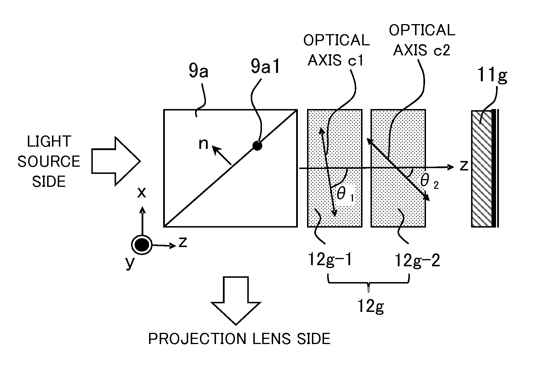
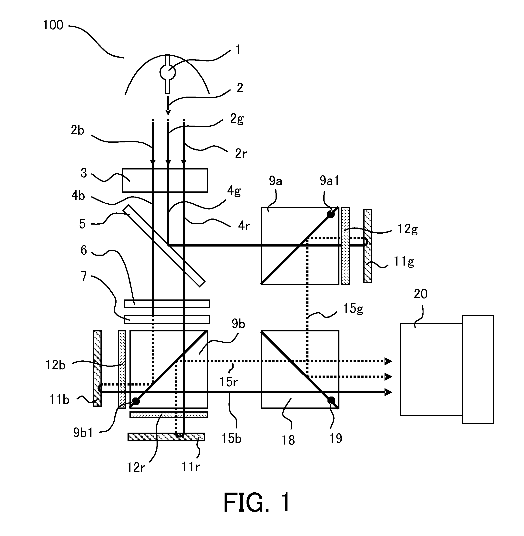
[0079]A projection display apparatus according to a first embodiment has the configurations illustrated in FIGS. 1 and 2, including two sapphire plates as phase compensation plates 12g, 12b, and 12r. Table 1 summarizes design values of each phase compensation plate. Each embodiment including this embodiment, light having a wavelength of 630 nm is used as Rch (red wavelength) light, light having a wavelength of 550 nm is used as Gch (green wavelength) light, and light having a wavelength of 450 nm is used as Bch (blue wavelength) light.

[0080]

TABLE 1dθθmax −φGch[um][deg]θminθave[deg]n0 / nePHASEPOLARIZATION36.277405701.770 / COMPENSATINGBEAM SPLITTER1.762PLATESIDEIMAGE DISPLAY370ELEMENT SIDEdθθmax −φRch[um][deg]θminθave[deg]n0 / nePHASEPOLARIZATION40.678405801.766 / COMPENSATINGBEAM SPLITTER1.757PLATESIDEIMAGE DISPLAY380ELEMENT SIDEdθθmax −φBch[um][deg]θminθave[deg]n0 / nePHASEPOLARIZATION27.677405701.781 / COMPENSATINGBEAM SPLITTER1.773PLATESIDEIMAGE DISPLAY370ELEMENT SIDE

[0081]From Table 1, the...

second embodiment

[0084]A projection display apparatus according to a second embodiment has configurations illustrated in FIGS. 1 and 9, and each of phase compensation plates 12g, 12b, and 12r includes a liquid crystal layer of which the alignment gradually varies in the depth direction as a refractive index anisotropic layer. Table 2 summarizes design values of the phase compensation plates:

[0085]

TABLE 2 dθθmax −φGch[um][deg]θminθave[deg]n0 / nePHASEPOLARIZATION31.3905363.501.58 / COMPENSATINGBEAM SPLITTER1.572PLATESIDEIMAGE DISPLAY370ELEMENT SIDEdθθmax −φRch[um][deg]θminθave[deg]n0 / nePHASEPOLARIZATION25.2905364  01.576 / COMPENSATINGBEAM SPLITTER1.568PLATESIDEIMAGE DISPLAY380ELEMENT SIDEdθθmax −φBch[um][deg]θminθave[deg]n0 / nePHASEPOLARIZATION35.3905363.501.588 / COMPENSATINGBEAM SPLITTER1.580PLATESIDEIMAGE DISPLAY370ELEMENT SIDE

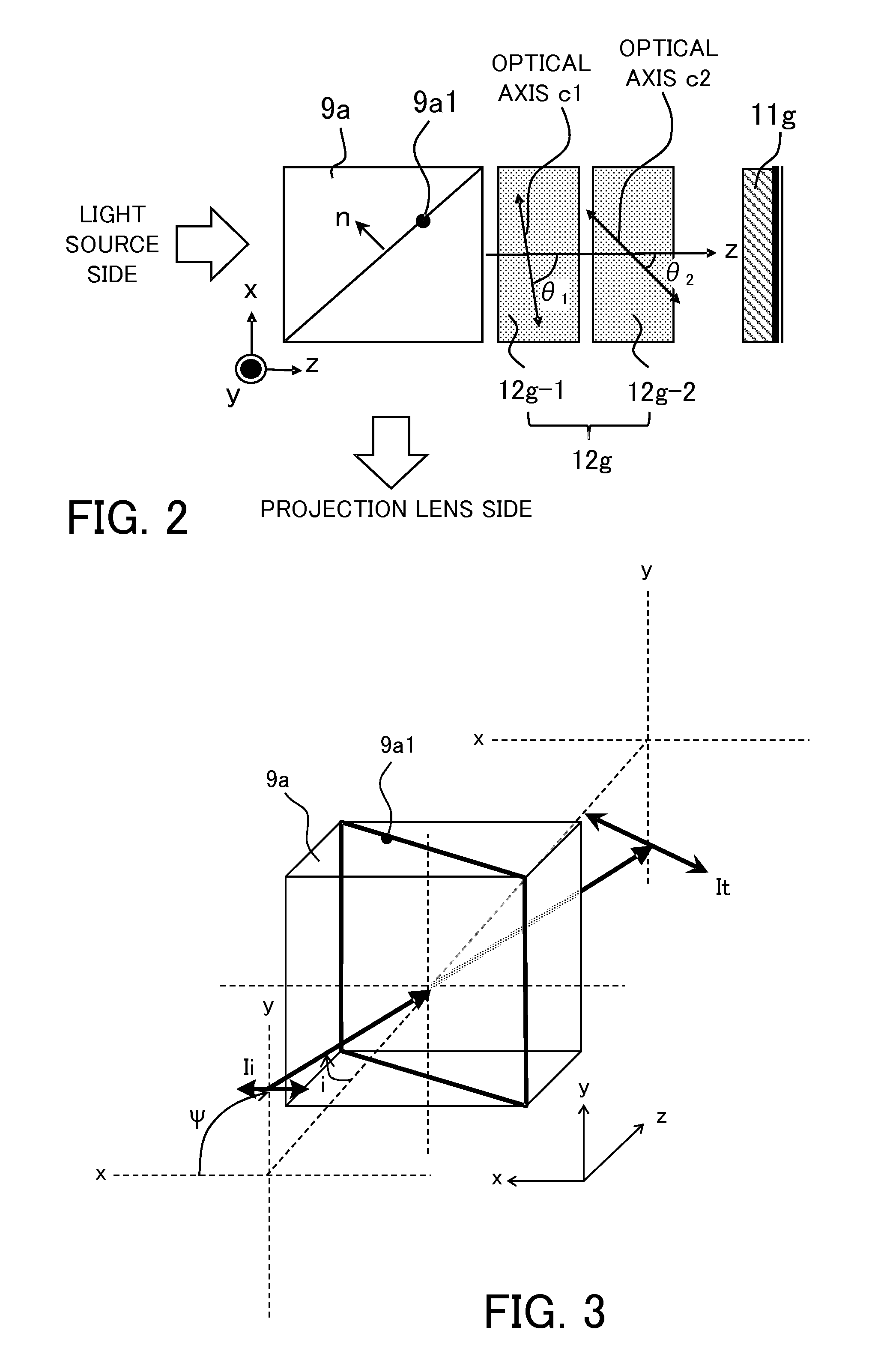
[0086]From Table 2, the optical axis of the phase compensation plate according to the second embodiment is located on the xz plane and satisfies the conditional expressions (1) to (...

third embodiment

[0088]A projection display apparatus according to a third embodiment has configurations illustrated in FIGS. 1 and 11, and three liquid crystal layers of which the alignment directions of the refractive index anisotropy gradually varies in the depth direction are laminated as phase compensation plates 12g, 12b, and 12r. Second phase compensation plates 13g, 13b, and 13r and third phase compensation plates 14g, 14b, and 14r are arranged between the phase compensation plates 12g, 12b, and 12r and the image display elements 11g, 11b, and 11r. Table 3 summarizes design values of the phase compensation plates:

[0089]

TABLE 3dθθmax −φGchGch[um][deg]θminθave[deg]n0 / nePHASEPOLARIZATION1220705501.555 / COMPENSATINGBEAM SPLITTER1.567PLATESIDEIMAGE DISPLAY900ELEMENT SIDEPHASEPOLARIZATION1290705501.555 / COMPENSATINGBEAM SPLITTER1.567PLATESIDEIMAGE DISPLAY200ELEMENT SIDEPHASEPOLARIZATION1290705501.555 / COMPENSATINGBEAM SPLITTER1.567PLATESIDEIMAGE DISPLAY200ELEMENT SIDESECOND PHASE 99090 1.517 / COMPENSA...


PUM

PropertyMeasurementUnit
angleaaaaaaaaaa
axial angleaaaaaaaaaa

Abstract

A projection display apparatus includes a polarization beam splitter, a first phase compensation plate including two layers, and a light modulator. Each layer has a constant axial angle, and an optical axis of each layer inclines with respect to the x axis in an xz plane. The axial angle of the layer closer to the polarization beam splitter among the two layers is larger than the axial angle of the layer farther from the polarization beam splitter. 20°≦θmax−θmin≦80° is satisfied where θmax is a maximum value of the axial angle and θmin is a minimum value of the axial angle. 40°≦θave≦70° is satisfied where θave is an average value of axial angles of the two layers.

Description

BACKGROUND OF THE INVENTION[0001]1. Field of the Invention[0002]The present invention relates to a projection display apparatus (image display apparatus) such as a liquid crystal projector.[0003]2. Description of the Related Art[0004]Since a polarization characteristic of a polarization beam splitter or a phase compensation plate (phase difference plate) of a projection display apparatus have incident angle dependency, polarized light in the entire incident angle range cannot be uniformly split, but the light partially becomes leaked light. In addition, since normally reflected light (0th order reflected light) and other order diffracted light beams which are generated through reflection of incident light on an image display element (image modulator) are reflected at different angles, the incident light is differently influenced by polarization elements, so that light leakage occurs. Due to the light leakage, a problem occurs in that the contrast of a projection image is deteriorate...

Claims


Application Information

Patent Timeline
Patent Type & Authority Patents(United States)
IPC IPC(8): G03B21/20G03B33/12G02F1/1335H04N9/31
CPCG03B21/2073G02F1/133528G03B33/12H04N9/3167
Inventor YAMAGUCHI, YUTAKA
Owner CANON KK
Why Eureka
Try Eureka