Lock assembly
a technology of lock components and mounting brackets, applied in the direction of gearing control, belts/chains/gearrings, braking systems, etc., can solve the problems of compromising the durability of the brake, subject to abuse treatment, and excessive load through the lock components and their mounting brackets
- Summary
- Abstract
- Description
- Claims
- Application Information
AI Technical Summary
Benefits of technology
Problems solved by technology
Method used
Image

Examples
first embodiment
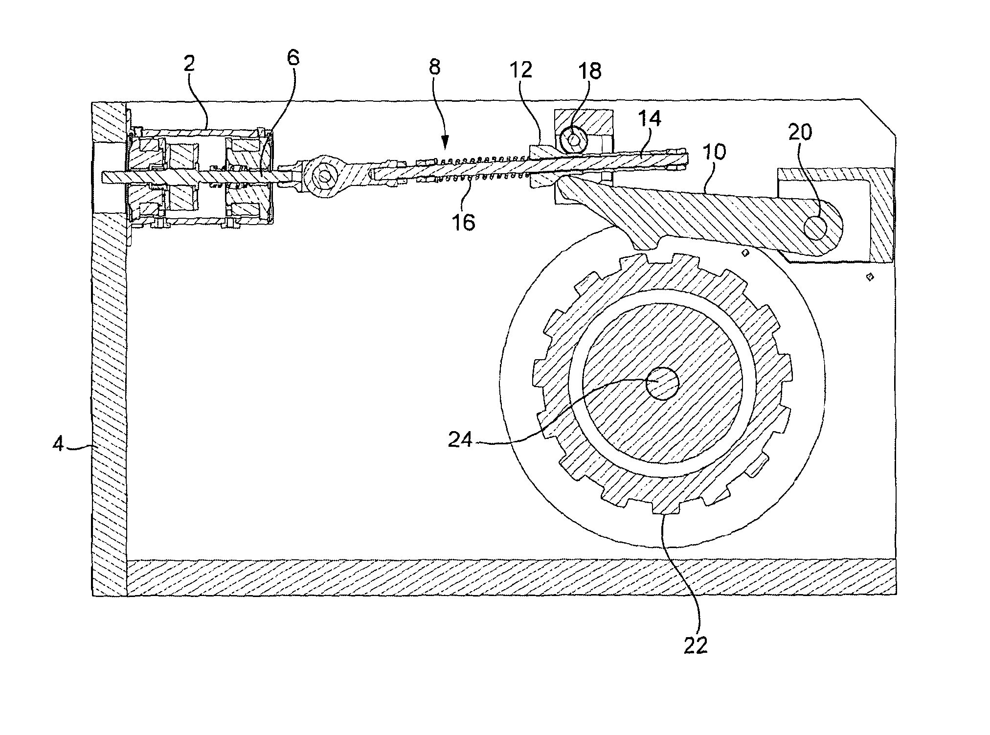
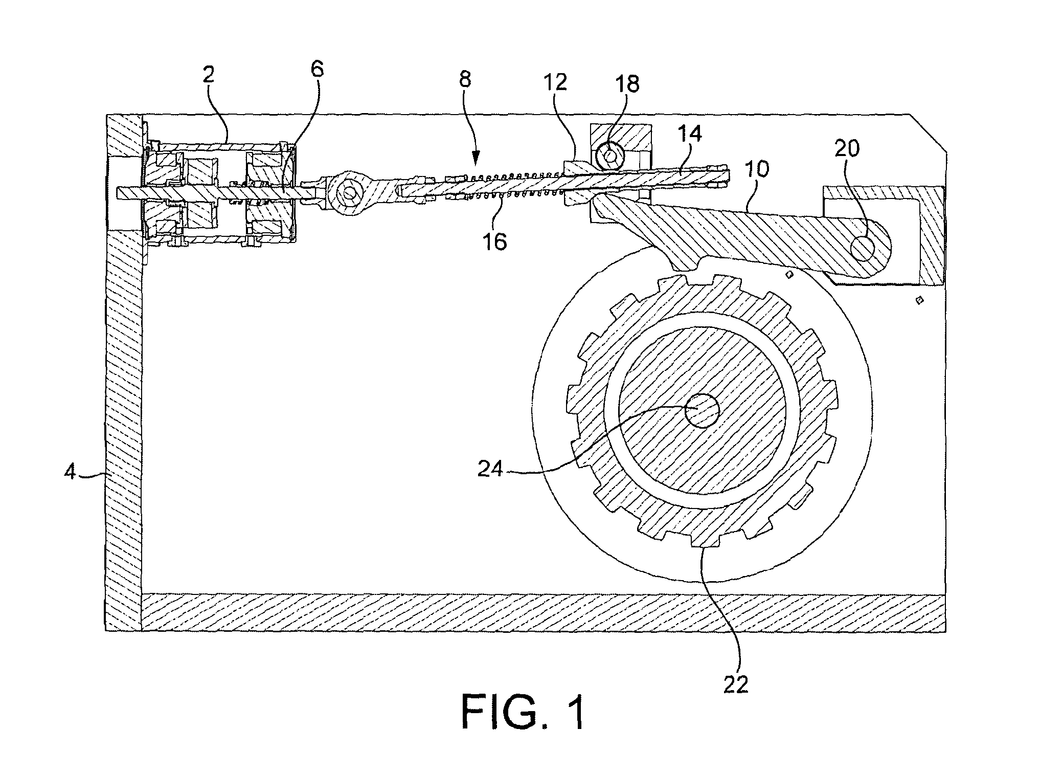
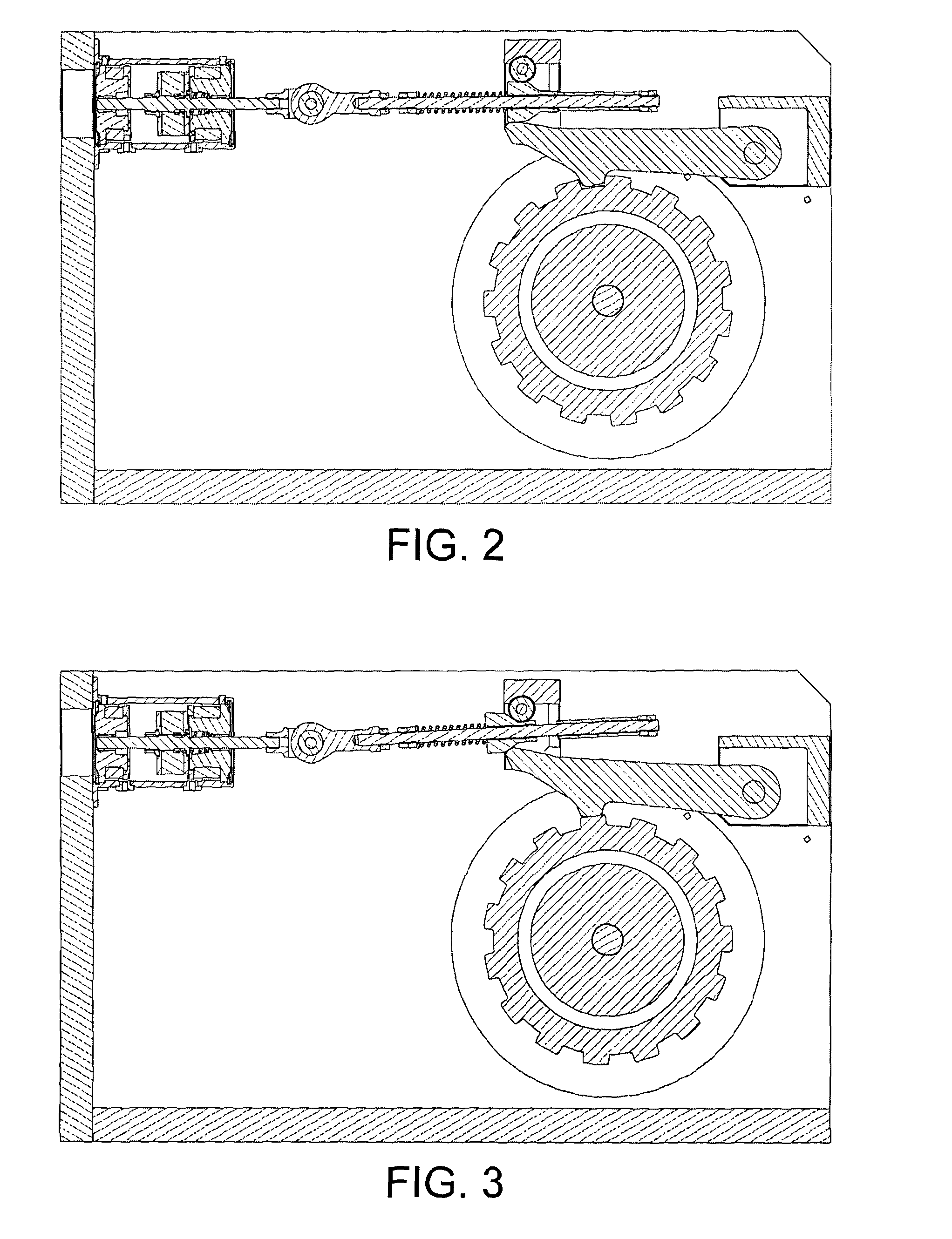
[0039]A first embodiment is depicted in FIGS. 1 to 3. As shown in FIG. 1, a bistable actuator 2 is mounted on a transmission casing 4. The impeller or actuation rod 6 of the actuator is coupled to a linkage 8. The linkage is in engagement with a locking arrangement in the form of a pawl 10.
[0040]Linkage 8 includes a cam 12 slidably mounted on a linear support 14. Cam 12 is coupled to a cam spring 16. Cam spring 16 acts to push the cam along support 14 in a direction away from the actuator 2. Cam 12 is in contact with a pin or roller 18 and the distal end of pawl 10. Pawl 10 is pivotably mounted on a pivot 20 supported on the transmission casing. Pawl 10 is resiliently biased against the cam 12 by a biasing arrangement not shown in FIG. 1.
[0041]In the cross-sectional side view of FIG. 1, it can be seen that cam 12 defines a tapered surface having two opposite sides with their spacing decreasing with distance from the actuator. This tapered surface joins to a portion of the cam having...
third embodiment
[0054]A third embodiment similar to that of FIGS. 6 and 7 is shown in FIGS. 8 and 9. In this case, the locking arrangement is in the form of a synchroniser 60. Sliding sleeve 62 and engagement ring 64 have respective continuous sets of complementary teeth 66 and 68 respectively. It operates in a similar manner to the embodiment of FIGS. 6 and 7.
[0055]In the embodiments of FIGS. 6 to 9, one end of the spring 44 is coupled to and moves with the actuation rod 6 of the actuator. The other end bears against the shift fork 46 when the actuator is moved into its engaged or locking position. Fork 46 in turn acts on the sliding sleeve 62.
[0056]Variations on the linkage between the actuator and the locking arrangement shown in FIGS. 8 and 9 are illustrated in FIGS. 10 and 11.
[0057]In FIGS. 10 and 11, the actuation rod 6 is connected to an elongate rail 61 which is slidingly received by an end stop 63. A shift fork 46 is slidably mounted on the rail. Spring 44 is engaged at one end by a flange...
fifth embodiment
[0061]the present locking arrangement is depicted in FIG. 13. The impeller 6 of actuator 2 is coupled to a locking arrangement in the form of a band brake 80. The band brake is in the form of a strip of material defining an incomplete circle in side view. One end 82 of the band is coupled to a fixed location, for example provided by a surrounding housing, providing a “ground reaction”84. The other end 86 of the band is coupled to the impeller 6. This coupling takes the form of a linkage 88 mounted (in a fixed manner or slidable axially) on one end of the impeller and pivotally mounted about a pivot 90 connected to end 86 of the band brake. An external spring 92 is provided between an end face of the actuator housing and an opposed surface 94 defined by linkage 88.
[0062]Band brake 80 is provided in concentric alignment with and around an inner rotor 96. When the locking arrangement is in its disengaged configuration, the inner rotor is free to rotate.
[0063]When the actuator impeller ...
PUM
 Abstract
Description
Claims
Application Information
 - R&D
- Intellectual Property
- Life Sciences
- Materials
- Tech Scout
- Unparalleled Data Quality
- Higher Quality Content
- 60% Fewer Hallucinations
Browse by: Latest US Patents, China's latest patents, Technical Efficacy Thesaurus, Application Domain, Technology Topic, Popular Technical Reports.
© 2025 PatSnap. All rights reserved.Legal|Privacy policy|Modern Slavery Act Transparency Statement|Sitemap|About US| Contact US: help@patsnap.com