Device for ventilating a fuel tank

Active Publication Date: 2016-01-26
AUDI AG
View PDF38 Cites 3 Cited by
  • Summary
  • Abstract
  • Description
  • Claims
  • Application Information

AI Technical Summary

Benefits of technology

[0006]Taking the foregoing into account, the invention is based on the object to improve a device of the aforementioned ty

Problems solved by technology

In the case of a rise of ambient temperatures, the previously describ

Method used


Image

  • Device for ventilating a fuel tank
  • Device for ventilating a fuel tank

Examples


Embodiment Construction

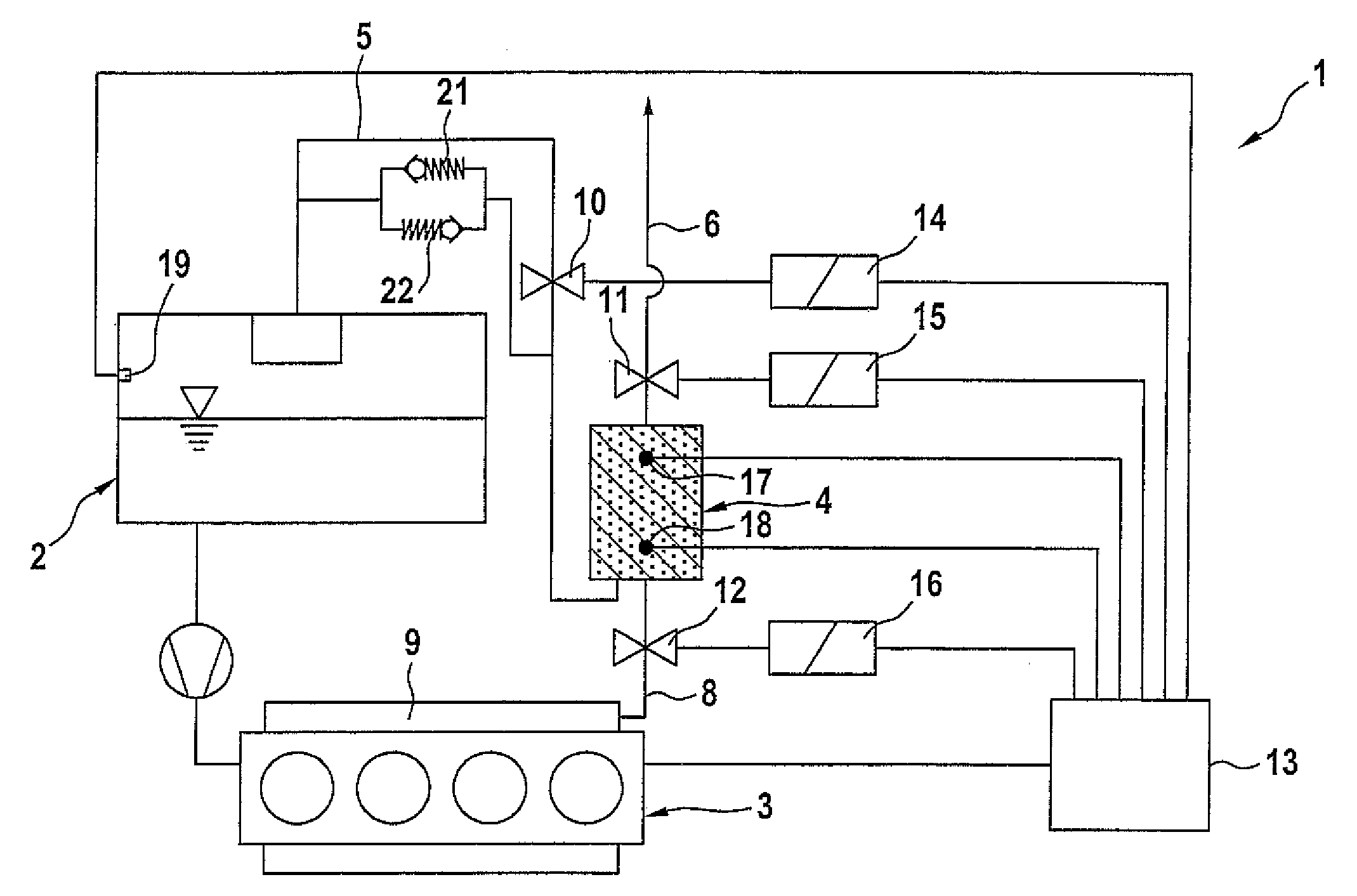
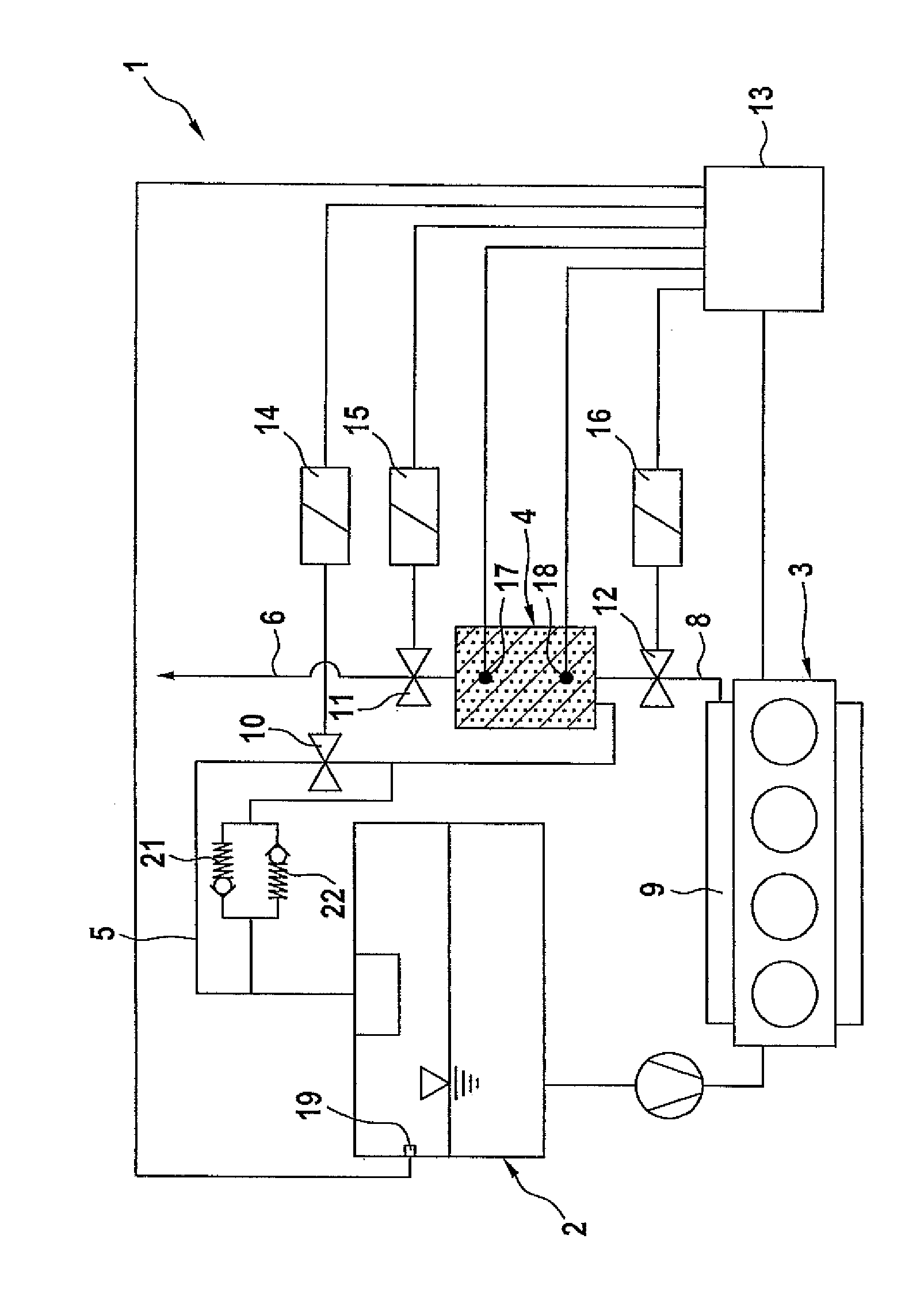
[0016]The device 1 according to the invention shown in the drawing serves for ventilating a fuel tank 2 of an internal combustion engine 3 which for example can be the internal combustion engine of a motor vehicle with hybrid drive or of a motor vehicle with automatic start-stop mechanism, or the device can be the internal combustion engine of a plug-in motor vehicle which is driven by an electric motor, which combustion engine serves as an auxiliary motor for charging a vehicle battery.

[0017]The device 1 includes an activated carbon filter 4, which is connected to the interior of the fuel tank 2 by a first gas 5 line which is also referred to as tank venting line, to the environment or the atmosphere by a second gas line 6 also referred to as ventilation line, and to an intake tract 9 by a third gas line 8 also referred to as regeneration line. The first and the third gas lines 5, 8 lead into the activated carbon filter 4 at one side, while the second gas line 6 leads into the acti...


PUM


Abstract

A device for ventilating a fuel tank of an internal combustion engine in particular of a fuel tank of an internal combustion engine of a motor vehicle includes an activated carbon filter and at least one valve which is controllable by a control unit. To prevent leakage of hydrocarbons into the environment without enlargement of the activated carbon filter the control unit controls the valve in dependence on a load factor of the activated carbon filter and/or in dependence on an operating cycle duration of the internal combustion engine.

Description

CROSS-REFERENCES TO RELATED APPLICATIONS[0001]This application claims the priority of German Patent Application, Serial No. 10 2010 055 319.0, filed Dec. 21, 2010, pursuant to 35 U.S.C. 119(a)-(d).BACKGROUND OF THE INVENTION[0002]The invention relates to a device for ventilating a fuel tank of an internal combustion engine, in particular of a fuel tank of an internal combustion engine of a motor vehicle.[0003]The fuel tank of motor vehicles is normally equipped with a tank ventilation device. On one hand, the tank ventilation device prevents that, in the case of a significant rise or drop of ambient temperatures, an undesired overpressure or negative pressure forms in the pressure-tight closed tank as a result of the evaporation of fuel caused by the rise of temperature or, respectively, condensation of fuel vapors caused by the drop of temperature. On the other hand, the tank ventilation device allows a gas mixture which is displaced by the fuel during refueling, to escape from the...

Claims


Application Information

Patent Timeline
IPC IPC(8): F02M25/08B60K15/03B60K15/035
CPCF02M25/0836B60K15/03519F02M25/08B60K2015/0319B60K2015/0321B60K2015/03514
Inventor HAGEN, HARALD
Owner AUDI AG
Why Eureka
Try Eureka