Hybrid electro-optical distributed software-defined data center architecture

a software-defined data center and hybrid technology, applied in the field of hybrid electrooptical distributed software-defined data center architecture, can solve the problems of packet transmission latency, high power consumption, limited bandwidth capacity,

Active Publication Date: 2016-01-26
NEC CORP
View PDF9 Cites 3 Cited by
  • Summary
  • Abstract
  • Description
  • Claims
  • Application Information

AI Technical Summary

Problems solved by technology

However, such technology consumes high power and offers limited bandwidth capacity.
Thus, due to the high communications requirements in data centers, an application of electrical switch fabrics leads to considerable power consumptions, introduces packet transmission latency, and increases operational cost.
However, optical switches suffer from high latency in a connection setup due to its low-speed switching.
Optical switch fabrics do not offer statistical multiplexing, may not be suitable to handle bursty traffic due to the limited buffering capacity.
Furthermore, the conventional architecture is of warehouse scale, which generates tremendous requirements of power supply, space, and cooling.
These architectures use MEMS with a large number of ports and, thus, are not scalable.
Additionally, if the MEMS fails, the architecture loses all optical connectivity, creating a single point of failure.
The architecture cannot support an aggregation of traffic from multiple TOR switches onto a single optical channel.
Thus, traffic cannot be statistically multiplexed onto a single optical channel and optical bandwidth cannot be shared among connections that connect different switches.

Method used


Image

  • Hybrid electro-optical distributed software-defined data center architecture
  • Hybrid electro-optical distributed software-defined data center architecture
  • Hybrid electro-optical distributed software-defined data center architecture

Examples


Embodiment Construction

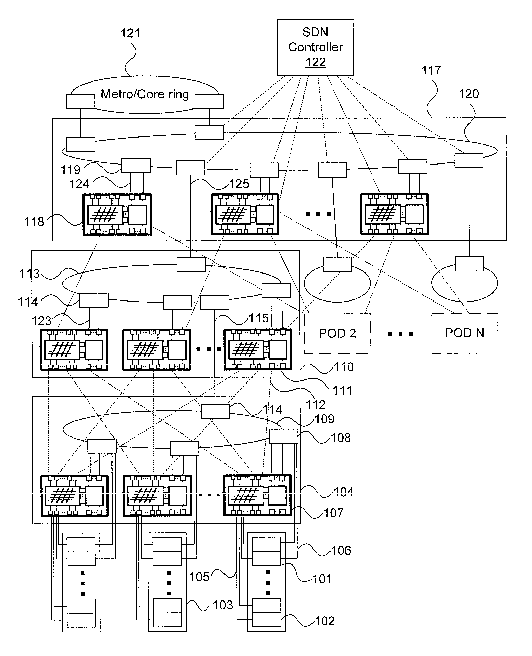
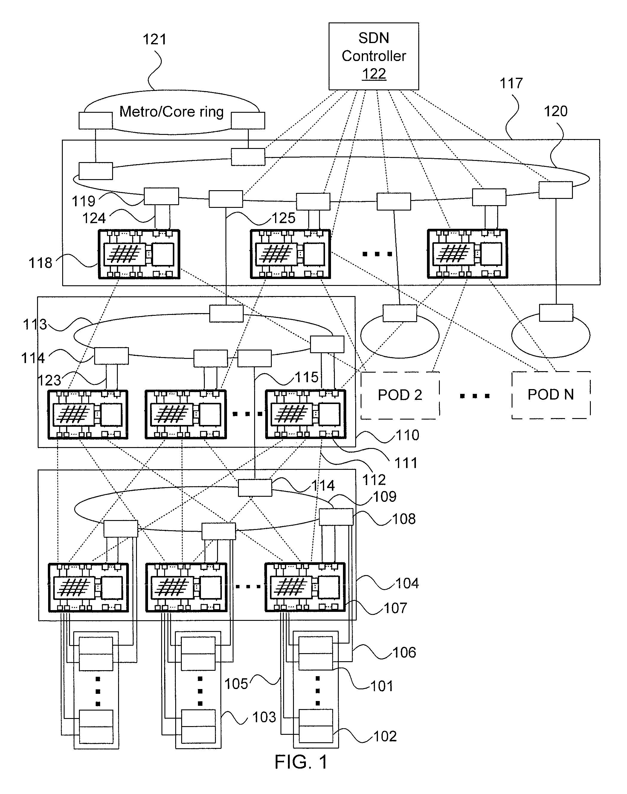
[0012]Embodiments of the present principles achieve the benefits of both electrical and optical switching technologies using a hybrid electro-optical, distributed, software-defined data center architecture in which interconnection of servers is provisioned through partially electrical switch fabrics and partially optical switch fabrics. The architecture set forth herein provides all-optical interconnectivity between some servers—referred to herein as “super servers”—of distributed data centers.

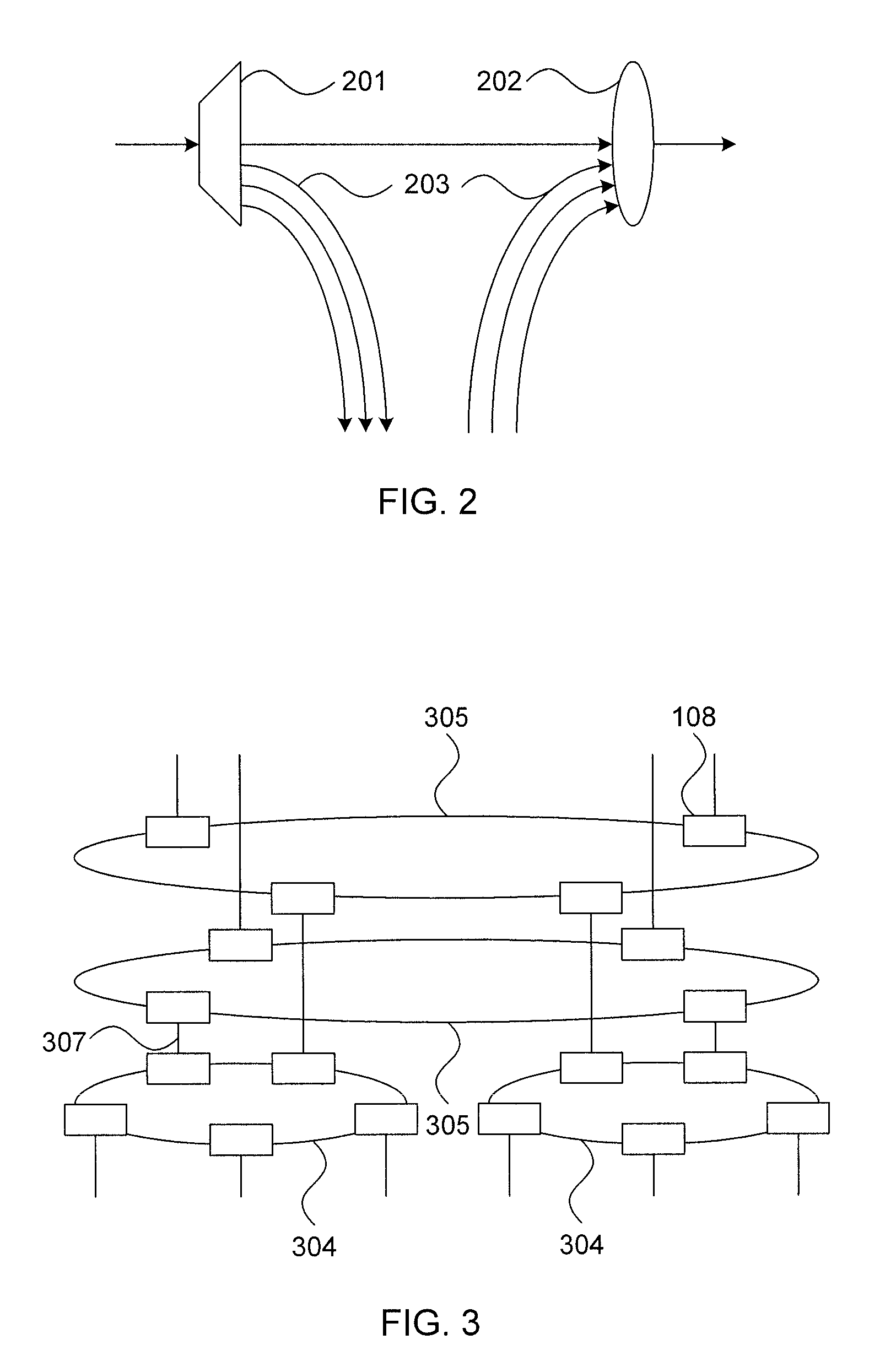
[0013]A hybrid electro-optical (HEO) switch interconnects servers using electrical and optical switching technologies. In an HEO switch, an electrical switch fabric is interconnected with an optical add / drop module using tunable dense wavelength division multiplexing (DWDM) optical pluggable transceiver modules. Electrical switch fabrics of the HEO switches are interconnected through a fat-tree architecture, while optical add / drop modules are interconnected through rings of optical fibers. The...


PUM


Abstract

A hybrid electro-optical data center system includes multiple tiers. A bottom tier has one or more bottom tier instances, with each bottom tier instance including one or more racks, an electro-optical switch corresponding to each rack, and a first bottom tier optical loop providing optical connectivity between the electro-optical switches of the respective bottom tier instance. At least one server within each rack is electrically connected to the respective electro-optical switch and at least one super-server within each rack is electrically and optically connected to the respective electro-optical switch. A top tier includes electro-optical switches, each electrically connected to an electro-optical switch in a respective bottom tier instance, a first top tier optical loop providing optical connectivity between the electro-optical switches of the top tier, and one or more optical add / drop modules providing optical connectivity between the first bottom tier optical loop and the first top tier optical loop.

Description

RELATED APPLICATION INFORMATION[0001]This application claims priority to provisional application number 61 / 909,446 filed Nov. 27, 2013, and the contents thereof are incorporated herein by reference.BACKGROUND OF THE INVENTION[0002]Due to emerging explosive growth of cloud-centric applications, the next generation data centers needs to achieve low latency, high throughput, and high resource efficiency. Furthermore, to offer such cloud services economically, operational costs such as power consumption and management complexity as well as the capital cost of these data centers should be reduced.[0003]To address the forthcoming heavy demands of cloud resources, the computing industry has continually investigates high-end servers with high numbers of processing cores integrated onto a single chip. In addition, to support the heavy traffic generated from servers, servers are equipped with high-speed network interface cards equipped with optical pluggable transceiver modules in addition to...

Claims


Application Information

Patent Timeline
Patent Type & Authority Patents(United States)
IPC IPC(8): H04J14/02H04Q11/00
CPCH04Q11/0005H04J14/0202H04Q11/0071H04Q2011/0052H04J14/0205H04J14/0212H04J14/0283
Inventor PATEL, ANKITKUMAR N.JI, PHILIP NANYIN, YAWEI
Owner NEC CORP
Why Eureka
Try Eureka