Carpet floor mat having plastic migrating prevention formation, and associated injection mold

a technology of floor mats and plastics, applied in the field of floor mats, can solve the problems of unsuitable vehicle floor mats, carpeting to become detached, and cost-intensive production of beadings, and achieve the effects of preventing the migration of plastics into the carpeting, reducing mold cycle time, and facilitating mass production

Active Publication Date: 2016-02-02
THERMOFLEX
View PDF23 Cites 9 Cited by
  • Summary
  • Abstract
  • Description
  • Claims
  • Application Information

AI Technical Summary

Benefits of technology

[0008]The above-listed needs are met or exceeded by the present injection molded carpet mat, featuring a web of carpet which is integrally formed with a supportive flexible mat. In the preferred embodiment, upper surfaces of the carpet and the surrounding mat are generally flush with each other. Further, the molds used to make such a mat are vertically oriented to face each other and separate along a vertical plane. Such disposition of the mold facilitates mass production and reduces mold cycle time. To retain the carpet web in position prior to the injection of liquid plastic, one half of the mold is subject to vacuum. The vacuum is maintained until the injection of the plastic and its eventual cooling and solidifying. A peripheral rib in the mold holds the carpet under pressure and also acts as a guard to prevent the migration of plastic into the carpeting. Further, a mold support landing is provided in the vacuum side of the mold to support an apertured vacuum plate to which the carpet is held upon the activation of vacuum.
[0014]In a still further embodiment, a method is provided for producing a carpet mat by injection molding. The method includes providing an injection mold including a cavity and a complementary core, each defining a portion of a mold recess for accommodating the finished carpet mat. Next, providing the cavity with a surface having at least one vacuum opening bordered by a peripheral retaining barrier, applying vacuum to the cavity, inserting a sheet of carpet into the mold recess of the cavity and against the surface so that the carpet is held in the recess by the vacuum. The method also includes providing a plurality of protrusion teeth in the core, the constructed and arranged for supporting the carpet sheet at an underside and along a peripheral edge, providing a complementary barrier in the cavity having a complementary inclined surface for receiving the peripheral edge of the carpet sheet, closing the cavity and core, thus sealing the mold recess, injecting a flowable supply of plastic into the mold recess. The protrusion teeth and the barrier exert sufficient pressure on upper and lower surfaces of the carpet mat at the peripheral edge for preventing migration of molten plastic into a nap surface of the carpet mat. After a specified period, the mold is opened, allowing the plastic to at least partially solidify.

Problems solved by technology

Such technology has been considered unsuitable for vehicle floor mats due, among other things, to the tendency for the carpeting to become detached from the backing material during normal use, especially at the peripheral edges.
However, such beadings are costly to produce and, moreover, have a considerable tendency to become soiled.
The lifetime of such a carpet mat is usually limited, typically because a beading has been damaged.
This undercut, on the one hand, solves the problem of the cutting tolerances, but, on the other hand, creates a new problem.
Moreover, carpet edges bordered in this way prove to be insufficiently flexible.
Furthermore, the operation of gluing the decorative material onto the carrier material represents an additional increase in price of the final product, and the adhesive power of the glue has been known to decrease over time and with extended use.
Another drawback of such techniques is that apertured grommets used to releasably secure these mats to the vehicle floor must be added by hand post-molding.
The '556 patent recognizes the problems inherent with injection molding carpet mats, including that the flowing resin migrates into the carpeting, and that the heat of the mold thins or otherwise degrades the carpeting during the molding process.
While the '556 disclosure allegedly resolved this problem, this technique has not been adopted by the commercial vehicle mat manufacturing industry.

Method used


Image

  • Carpet floor mat having plastic migrating prevention formation, and associated injection mold
  • Carpet floor mat having plastic migrating prevention formation, and associated injection mold
  • Carpet floor mat having plastic migrating prevention formation, and associated injection mold

Examples


Embodiment Construction

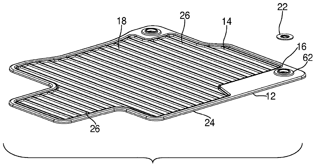
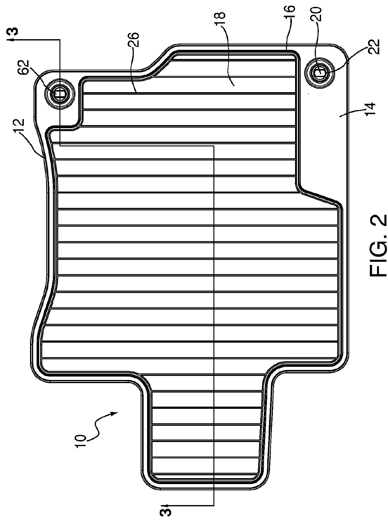
[0048]Referring to FIGS. 1-6, the present injection molded carpet mat is depicted and generally designated 10. A flexible base 12 is made of bendable, injection moldable materials, including but not limited to polypropylene, ABS copolymers, TPE, thermoplastic rubbers or the like, as are well known in the art. The base 12 has an upper surface 14 having a peripheral edge 16 defining a carpet recess 18. Also found on the peripheral edge 16 is at least one grommet aperture 20 provided with a grommet 22 used for securing the mat 10 to a lug on a vehicle floor as is known in the art (not shown). Opposite the upper surface 14 is a lower mat surface 24. As seen in FIGS. 1 and 2, the carpet recess 18 is preferably provided with a plurality of spaced, parallel ribs 26 for strength and more efficient use of material.

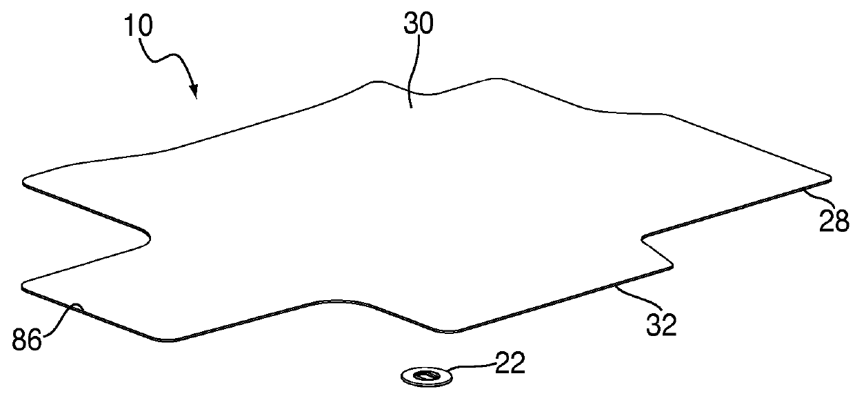
[0049]A sheet of carpet 28 is shaped to be inserted into the carpet recess 18, and has an upper nap side 30 and an opposite backing or attachment side 32. An important feature of t...


PUM

PropertyMeasurementUnit
flexibleaaaaaaaaaa
angleaaaaaaaaaa
perimeteraaaaaaaaaa

Abstract

An injection molded carpet mat includes a flexible base having an upper surface defining a carpet recess, and an opposite lower surface. A carpet sheet is secured in the carpet recess by being integrally formed with the base, and having a napped top surface, a bottom surface and a peripheral edge. The lower base surface having a plurality of spaced ribs supporting the carpet bottom surface adjacent the peripheral edge and defining a track on the lower base surface corresponding to the peripheral edge of the carpet sheet.

Description

RELATED APPLICATION[0001]This application is a CIP of, and claims 35 USC §120 priority from, U.S. Ser. No. 12 / 850,931 filed Aug. 5, 2010 and entitled FLOOR MAT WITH INTEGRALLY MOLDED CARPETING, AND ASSOCIATED INJECTION MOLD now U.S. Pat. No. 8,454,873.BACKGROUND OF THE INVENTION[0002]The present invention relates to floor mats designed for being laid upon existing flooring, such as used in vehicles for protecting carpeting. More specifically, the present invention relates to an improved floor mat provided with carpeting, and a process for making same.[0003]Conventional floor matting, as used in runners for commercial and residential flooring, involves laminating a web of carpeting upon a complementary web of rubber-like backing material. The two webs are adhered to each other using heat and / or chemical adhesives as is well known in the art. Such technology has been considered unsuitable for vehicle floor mats due, among other things, to the tendency for the carpeting to become detac...

Claims


Application Information

Patent Timeline
Patent Type & Authority Patents(United States)
IPC IPC(8): B60N3/04B29C45/26B29C45/14B29L31/00
CPCB60N3/048B29C45/14065B29C45/14336B29C45/14786B29C45/26B60N3/044B60N3/046B29C2045/14155B29C2045/14934B29L2031/7324Y10T428/23979
Inventor PRICE, ROBERT A.MILELLA, JR., MICHAEL J.REBAND, DAVID A.MAZUR, KARL J.MILLER, ROBERT M.
Owner THERMOFLEX
Why Eureka
Try Eureka