Method and device for detecting an analyte in a body fluid

a body fluid and analyte technology, applied in the field of body fluid detection methods and devices, can solve the problems of increasing the effort to further reduce the sample volume to be applied to the test field, unable to detect blank values, and unable to achieve the effect of detecting blank values

Active Publication Date: 2016-02-09
ROCHE DIAGNOSTICS OPERATIONS INC
View PDF18 Cites 4 Cited by
  • Summary
  • Abstract
  • Description
  • Claims
  • Application Information

AI Technical Summary

Benefits of technology

[0030]The sequence of corrected images, in the following, is also referred to as the corrected sequence. By obtaining the corrected sequence according to the present invention, the corrected sequence may be used for detecting the at least one analyte, such as for observing the—optionally time-dependent—change of at least one optically detectable property of the test field due to the detection reaction of the test chemistry with the analyte to be detected. By correcting the image sequence, a high degree of robustness and reliability may be achieved, as opposed to conventional techniques, and most of the above-mentioned shortcomings of known methods and devices are overcome.
[0128]In this way or another way, by evaluating significant changes of the corrected images before / during sample application and after sample application, the region of interest may easily be determined as a set or group of coordinates or positions within the corrected images. Thus, the region of interest may easily be represented by a binary matrix indicating whether a pixel of the corrected images belongs to the region of interest or not. This binary mask or binary matrix on a pixel-by-pixel basis may precisely define the region of interest even for complex geometries of the micro-samplers, as opposed to traditional methods which, typically, make use of definitions of regions of interest by rather simple geometries, such as circular geometries and / or rectangular geometries.

Problems solved by technology

Despite the progress achieved by the above-mentioned known methods and devices, some major challenges remain regarding the precision of the analyte detection.
Thus, there is a constant effort for further reducing the sample volume to be applied to the test fields.
A further technical challenge resides in a precise normalization of the measurement data acquired by the optical detectors or detector arrays.
Specifically in case the precise location of sample application onto the test field is unknown, the determination of a blank value, however, is rather challenging, since the blank value itself may be dependent on the precise location on the test field.
Thus, in most cases, either blank values in different locations than the location of the sample application on the test field will have to be used, leading to a high uncertainty of the blank value, or, a large number of images of the test field before and after sample application will have to be stored and evaluated, leading to high need for data storage and calculation resources.
The latter, however, is specifically disadvantageous for hand-held test devices which typically provide rather limited hardware capabilities.
This type of sample transfer, however, typically implies dynamic processes involving moving parts, which may lead to a displacement of the test fields or parts thereof.
Thus, pressing the micro-samplers onto the test fields may lead to a distortion and / or displacement of the test fields.
Thus, during use and handling of the test devices, specifically during measurements, the test fields may move, thereby creating inaccuracies regarding acquisition of the blank values and regarding the determination of the actual area of the test fields to be evaluated for analyte determination.

Method used


Image

  • Method and device for detecting an analyte in a body fluid
  • Method and device for detecting an analyte in a body fluid
  • Method and device for detecting an analyte in a body fluid

Examples


Embodiment Construction

[0215]For the purposes of describing and defining the present invention it is noted that terms like “preferably”, “commonly”, and “typically” are not utilized herein to limit the scope of the claimed invention or to imply that certain features are critical, essential, or even important to the structure or function of the claimed invention. Rather, these terms are merely intended to highlight alternative or additional features that may or may not be utilized in a particular embodiment of the present invention.

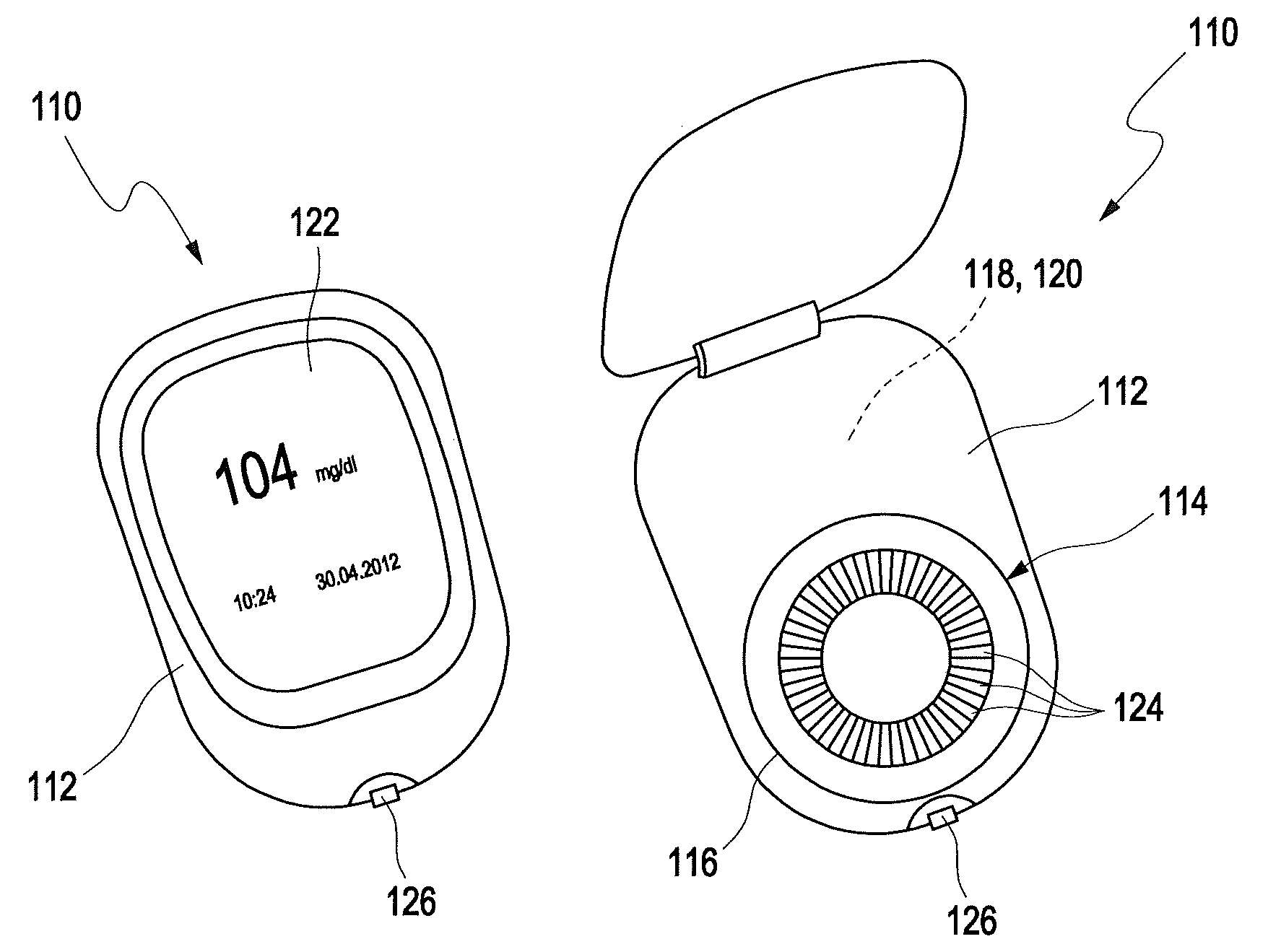
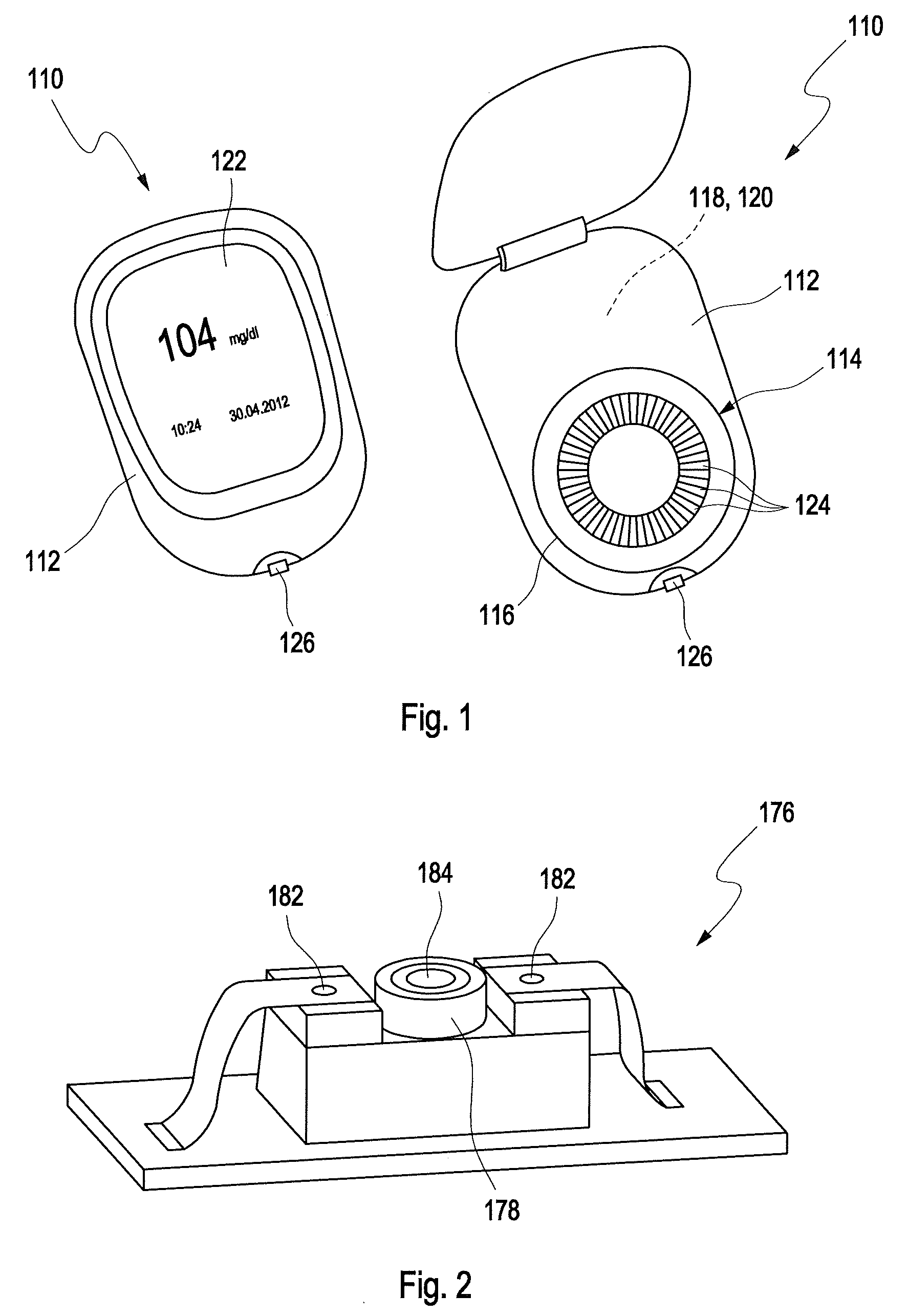
[0216]In FIG. 1, a potential test system 110 for detecting at least one analyte in at least one sample of a body fluid is disclosed in two different states, wherein the test system 110 on the left hand side in FIG. 1 is shown in a closed state, and on the right hand side in an opened state. The test system 110 comprises a device 112 for detecting at least one analyte in at least one sample of a body fluid and, as an example, a magazine 114 received in a receptacle 116 of the dev...


PUM

PropertyMeasurementUnit
volumesaaaaaaaaaa
volumesaaaaaaaaaa
timeaaaaaaaaaa

Abstract

A method for detecting at least one analyte in at least one sample of a body fluid is disclosed. Therein, at least one test element (124) is used, the at least one test element (124) having at least one test field (162) with at least one test chemistry (154) is used, wherein the test chemistry (154) is adapted to perform at least one optically detectable detection reaction in the presence of the analyte. The method comprises acquiring an image sequence of images of the test field (162) by using at least one image detector (178). Each image comprises a plurality of pixels. The method further comprises detecting at least one characteristic feature of the test field (162) in the images of the image sequence. The method further comprises correcting a relative position change between the image detector (178) and the test field (162) in the image sequence by using the characteristic feature, thereby obtaining a sequence of corrected images.

Description

CROSS-REFERENCES TO RELATED APPLICATION(S)[0001]This application is a continuation of international application number PCT / EP2013 / 062499, filed Jun. 17, 2013, which claims priority to European patent application number 12173121.0, filed Jun. 22, 2012, each of which is incorporated by reference herein in their entirety.FIELD OF THE INVENTION[0002]The present application refers to a method, a device and a test system for detecting at least one analyte in a sample of a body fluid. The invention further relates to a computer program with program means for executing the method according to the invention, as well as to a computer system and to a storage medium. Methods, devices, test systems, computer programs and computer systems according to the present invention may be used in medical diagnostics, in order to qualitatively or quantitatively detect one or more analytes in one or more body fluids. Other fields of application of the present invention are possible.RELATED ART[0003]In the f...

Claims


Application Information

Patent Timeline
Patent Type & Authority Patents(United States)
IPC IPC(8): G06K9/00G06K9/32G06T7/00C12Q1/54G01N21/84G01N21/78G01N21/77
CPCG01N21/78C12Q1/54G01N21/8483G06K9/00134G06K9/3208G06T7/0026G01N2021/7769G06K2009/3225G06T2207/30024Y10T436/144444G06V20/693G06V10/242G06V10/245G06T7/32G01N21/77G01N21/7703G01N21/84
Inventor DICKOPF, KAI
Owner ROCHE DIAGNOSTICS OPERATIONS INC
Why Eureka
Try Eureka