
Injection molded product and method of manufacturing the same

a technology of injection molding and product, which is applied in the direction of electric connection formation of printed elements, protective material radiating elements, instruments, etc., can solve the problems of inability to reliably make electrical connections, abnormal external appearance, and risk that users will no longer identify with the product, so as to reduce the number of manufacturing steps and the lead time, and ensure the electrical connection. , the effect of low cos

Active Publication Date: 2016-02-09
NISSHA PRINTING COMPANY
View PDF19 Cites 0 Cited by
  • Summary
  • Abstract
  • Description
  • Claims
  • Application Information

AI Technical Summary

Benefits of technology

The present invention provides an injection molded product and a method of manufacturing the same using an electrically conductive adhesive between the contact pin and the electrode pattern, which reliably makes the electrical connection. Compared to other methods, the present invention does not require ultrasonic pressing and drying the solvent, reducing the number of manufacturing steps and lead time, and minimizing the cost of manufacturing without external appearance abnormalities. Additionally, the present invention does not require an insertion of the contact pin after formation, preventing issues such as pin traces, base film splitting, and contact pin passing through the base film and film.

Problems solved by technology

In conventional insert molding, there are cases wherein the electrical connection between the contact pin and the electrode pattern is insufficient and therefore the electrical connection cannot be reliably made, which is a problem.
However, because the electrically conductive adhesive is injected into the bottom part of the hole, the solvent in the electrically conductive adhesive tends not to volatilize; therefore, because it takes time for the adhesive to dry and harden, the base film dissolves or swells owing to the action of the solvent, which creates abnormalities in the external appearance.
In addition, to inject the electrically conductive adhesive into the hole, the hole diameter must be larger than the diameter of a tip needle of a dispenser; however, if the hole diameter is increased, there are cases in which a location corresponding to a portion of the hole appears to swell owing to a shrinkage differential between the base film and the molded resin at a peripheral part of the hole; in terms of the external appearance, too, there is a risk that users will no longer identify with the product.
In addition, there are problems in that, for example, the electrode pattern tears owing to the contact pin being inserted into the hole and, attendant therewith, the base film splits and, depending on the case, the contact pin may adversely pass through the electrode pattern and the base film.
Furthermore, there is a problem in that the process becomes complicated because the hole diameter is made narrower than the diameter of the contact pin so that the contact pin to be inserted does not lack stability, and therefore, when the contact pin is to be inserted, the contact pin must be pressed in while imparting ultrasonic vibration to the contact pin and while softening the molded resin of the hole part with which the circumference of the pin makes contact.

Method used


Image

  • Injection molded product and method of manufacturing the same
  • Injection molded product and method of manufacturing the same
  • Injection molded product and method of manufacturing the same

Examples


first embodiment

(First Embodiment)

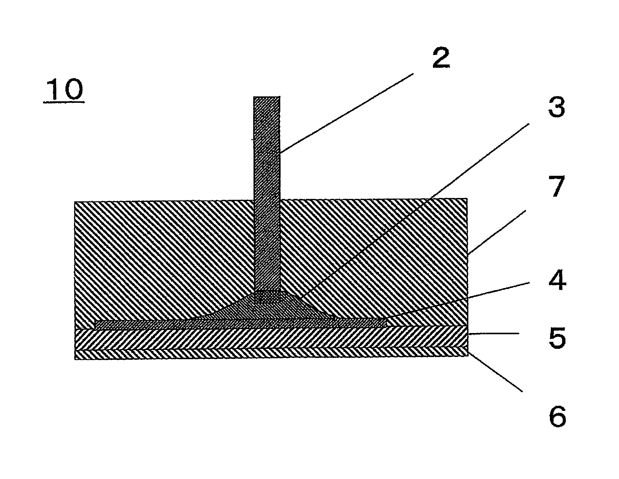
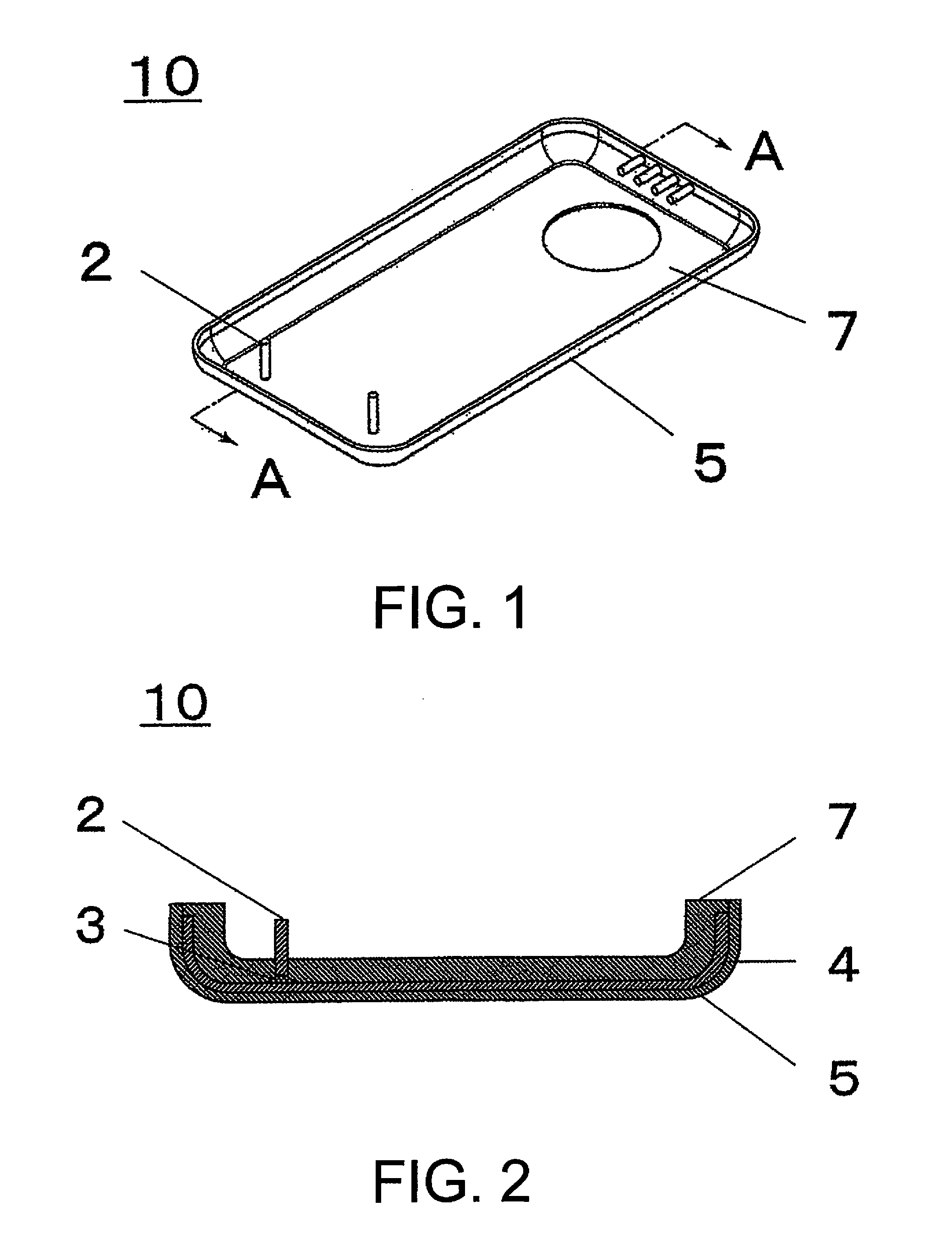
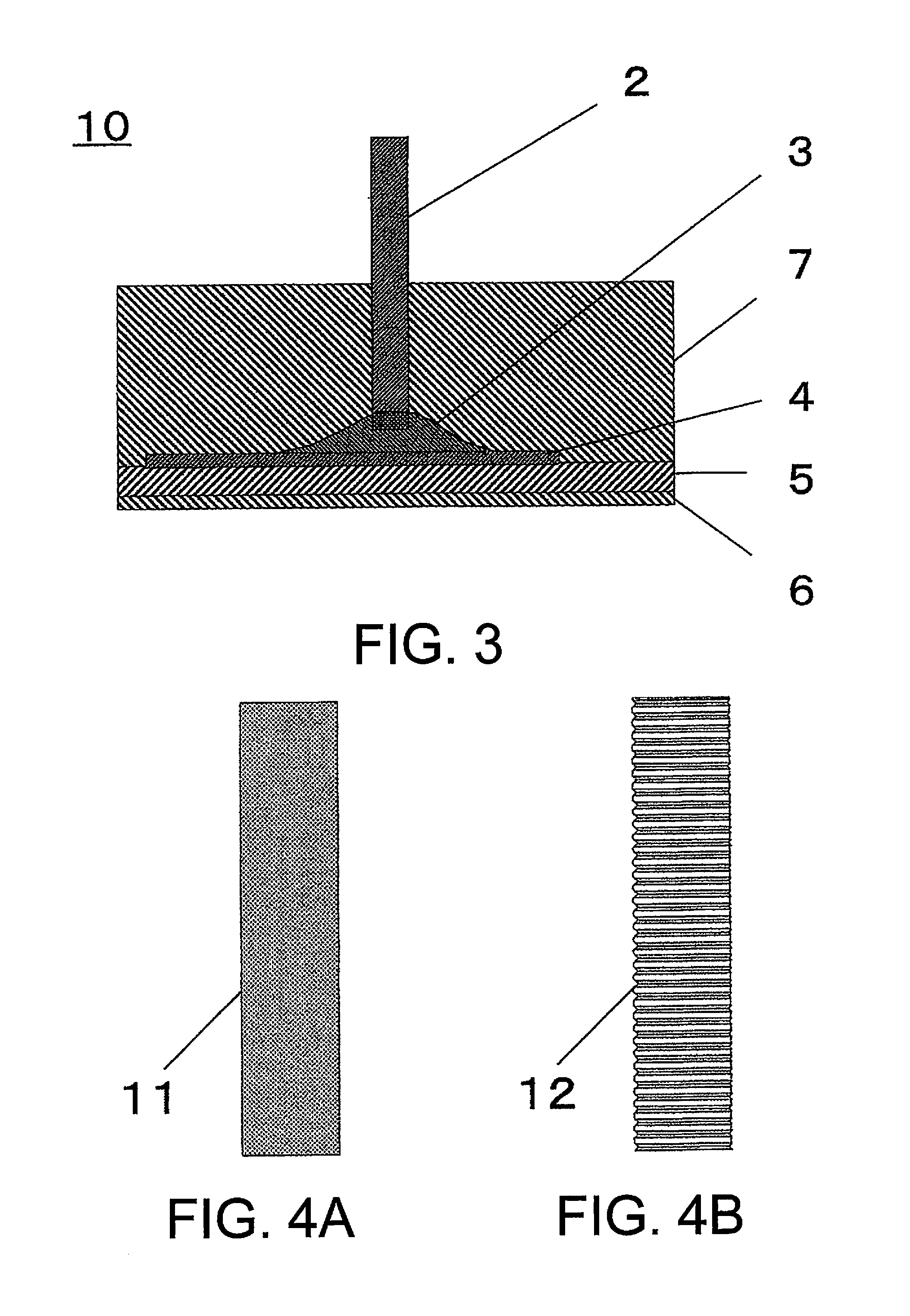
[0046]FIG. 1 is an oblique view that shows an injection molded product 10 according to a first embodiment of the present invention. FIG. 2 is a cross sectional view taken along the A-A line of the injection molded product 10 in FIG. 1. The injection molded product 10 according to the first embodiment shown in FIG. 1 and FIG. 2 comprises contact pins 2, an electrically conductive adhesive 3, an electrode pattern 4, a base film 5, and a molded resin 7. Furthermore, in addition to the abovementioned configuration, there may also be an insulative layer, a shield layer, a peel-off layer that protects the surface from scratches, a design layer that expresses a design, an anchor layer that improves adhesion to the molded resin 7, and the like.

[0047]FIG. 3 is an enlarged cross sectional view that shows the configuration of the injection molded product 10 according to the first embodiment. The injection molded product 10 is provided with: the base film 5; the electrode patt...

second embodiment

(Second Embodiment)

[0065]Next, a method of manufacturing the injection molded product 10 according to the second embodiment will be explained, with reference to FIGS. 8(a)-(d). FIGS. 8(a)-(d) include cross sectional views that show each step of the method of manufacturing the injection molded product 10 according to the second embodiment of the present invention.

[0066](1) Prepare an injection molding mold, which comprises a fixed mold 22 and a movable mold 21 that is capable of being in contact with and separating from the fixed mold 22 (FIG. 8(a)).

[0067](2) Mount the base film 5, on which the electrode pattern 4 and the electrically conductive adhesive 3 have been provided, on an inner surface of the movable mold 21 (FIG. 8(a)). It is preferable to dry the electrically conductive adhesive 3. In addition, the electrically conductive adhesive 3 may be an electrically conductive adhesive that comprises the electrically conductive filler, the binder, and the solvent. And it is preferab...


PUM

PropertyMeasurementUnit
widthaaaaaaaaaa
thicknessaaaaaaaaaa
thicknessaaaaaaaaaa

Abstract

An injection molded product in which an electrical connection between a contact pin and an electrode pattern is sufficient, and a method of manufacturing the same, are provided. The injection molded product comprises: a base film; an electrode pattern, which is formed on the base film; an electrically conductive adhesive, which is formed on an upper surface of the electrode pattern; a contact pin, which contacts the electrically conductive adhesive, is electrically connected to the electrode pattern via the electrically conductive adhesive, and is electrically conductive; and a molded resin, which is injection molded along the base film such that the electrically conductive adhesive and part of the contact pin are embedded.

Description

CROSS-REFERENCE TO RELATED APPLICATION[0001]This U.S. National stage application claims priority under 35 U.S.C. §119(a) to Japanese Patent Application No. 2012-123261, filed in Japan on May 30, 2012, the entire contents of Japanese Patent Application No. 2012-123261 are hereby incorporated herein by reference.BACKGROUND[0002]1. Field of the Invention[0003]The present invention relates to an injection molded product that electrically connects a contact pin and an electrode pattern, and to a method of manufacturing the same. The present invention particularly relates to an injection molded product that electrically connects a contact pin and an electrode pattern using an electrically conductive adhesive, and to a method of manufacturing the same.[0004]2. Background Information[0005]As a method of electrically connecting a contact pin and an electrode pattern, the conventional art includes insert molding. In insert molding, an electrode pattern is provided on a base film and the elect...

Claims


Application Information

Patent Timeline
Patent Type & Authority Patents(United States)
IPC IPC(8): H05K7/02H05K3/40G06F1/16H05K3/00H01R4/04H01Q1/40H01R43/24H01Q1/24B29C45/14H05K3/10H05K1/02B29L31/34G06F3/044
CPCG06F3/044B29C45/14065B29C45/14467B29C45/14639G06F1/16H01Q1/243H01Q1/40H01R4/04H01R43/24H05K3/0014H05K3/101H05K3/4015H05K7/02B29C2045/14114B29L2031/3437B29L2031/3481G06F2203/04112H05K1/0284H05K2201/0999H05K2201/09118H05K2201/10318G06F3/0445H01Q1/38
Inventor YAMAZAKI, SEIICHIHIGASHIKAWA, TOSHIHIROMATSUZAKI, TOMOHIROKARIYA, MASAHIKO
Owner NISSHA PRINTING COMPANY
Learn More