Chromatic range sensor including high sensitivity measurement mode

Active Publication Date: 2016-02-16
MITUTOYO CORP
View PDF9 Cites 9 Cited by
  • Summary
  • Abstract
  • Description
  • Claims
  • Application Information

AI Technical Summary

Benefits of technology

[0010]According to embodiments of the present invention, a method for operating a CRS system to perform a workpiece height measurement of a low reflectivity workpiece surface is provided. In one embodiment, the CRS system may comprise a chromatic point sensor (CPS) system including an optical pen. In one aspect, the CRS system includes high sensitivity measurement mode in which the CRS system can be operated at a lower sampling rate (lower than conventionally available sampling rates) to measure a workpiece surface having low reflectivity. The CRS system operated at such l

Problems solved by technology

Some workpiece surfaces may have particularly low reflectivity, (e.g., matte black or transparent workpieces) and provide a low signal, which is insufficient to produce a significant (valid) wavelength peak that can be well-estimated in a resulting intensity profile received by the spectrometer's detector array.
However, increasing an exposure time beyond a certain level may cause significant or complete saturation of some of the pixels in the spectrometer's detector array regardless of whether there is workpiece surface located to produce a corresponding wavelength, or not.
Pixels saturated to at least a “saturation threshold” level cannot provide a valid wavelength peak signal, due to insufficient peak height to support an accurate peak location estimate.
If a workpiece surface is located at a distance at which a specific wa

Method used


Image

  • Chromatic range sensor including high sensitivity measurement mode
  • Chromatic range sensor including high sensitivity measurement mode
  • Chromatic range sensor including high sensitivity measurement mode

Examples


Embodiment Construction

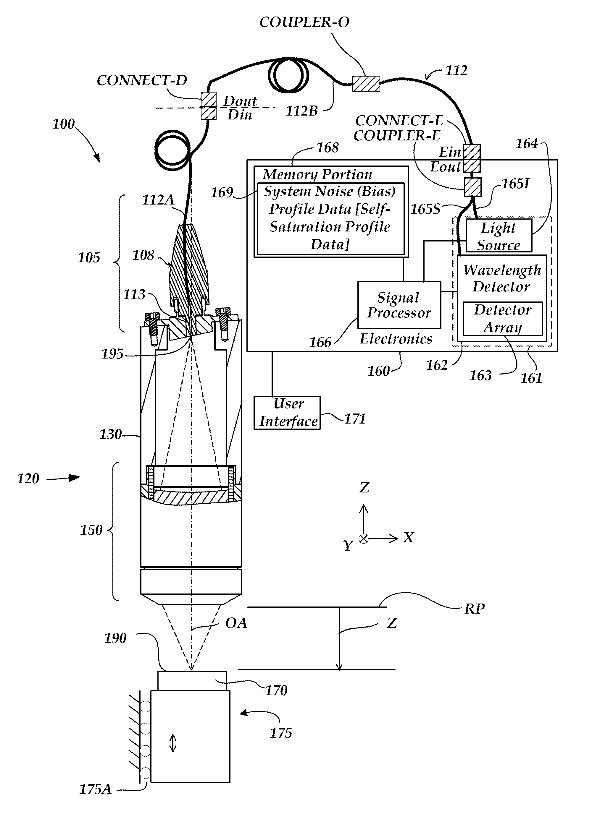
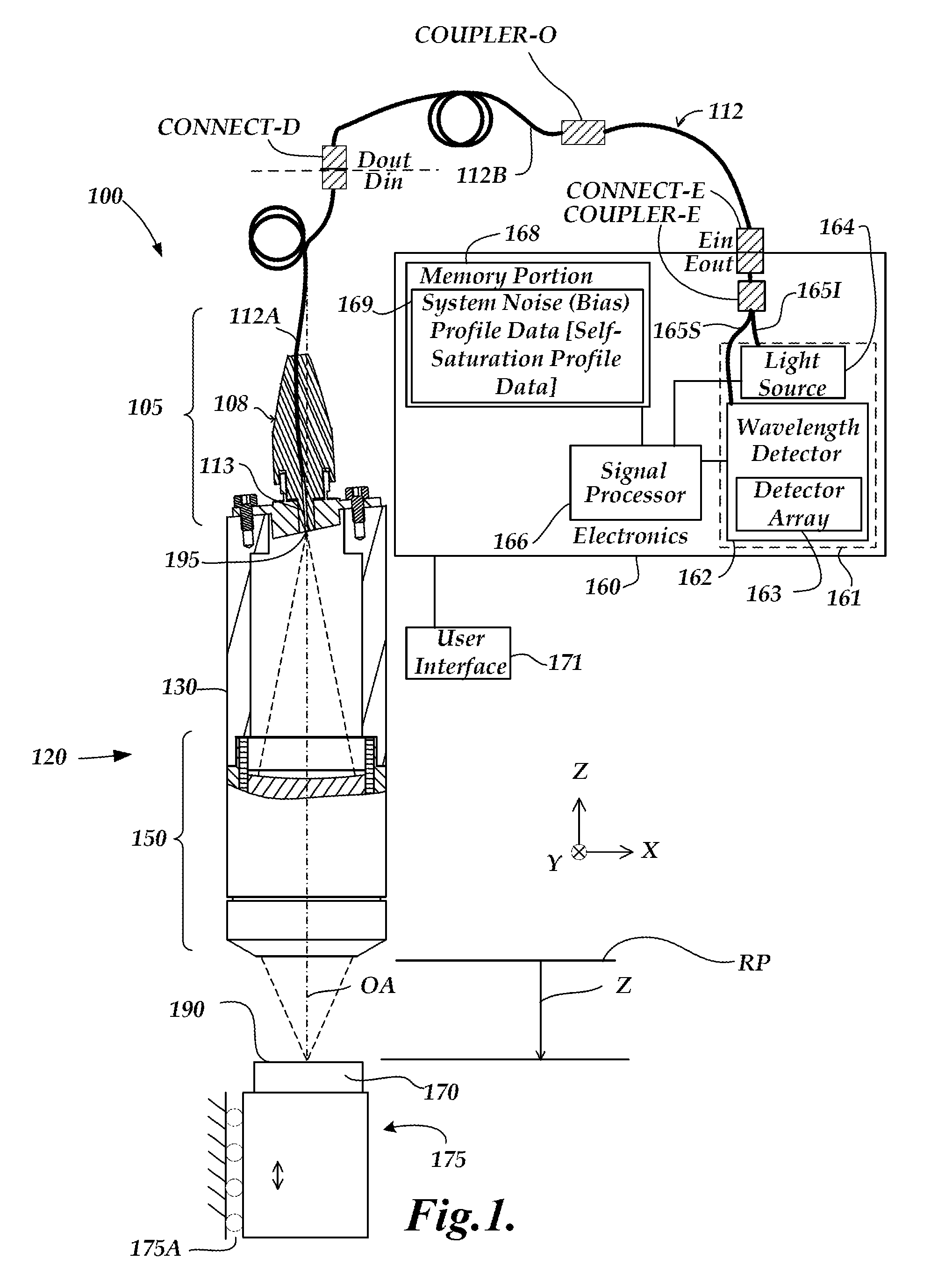
[0024]FIG. 1 is a block diagram of one exemplary embodiment of a chromatic range sensor (CRS) system 100, including an optical element 120 (e.g., an optical pen), an electronics portion 160, and a user interface portion 171. The embodiment of the electronics portion 160 includes a signal processor 166, a memory portion 168 and a source and detector subsystem 161 comprising a wavelength detector 162, and a broadband light source 164. The CRS system 100 shown in FIG. 1 is a chromatic point sensor (CPS) system which measures a single measurement point at a time. In various embodiments, the wavelength detector 162 includes a detector array 163 of a spectrometer. The detector array 163 may comprise a plurality of pixels distributed along a measurement axis of the wavelength detector 162, wherein the plurality of pixels receive respective wavelengths and provide output spectral profile data. The electronics portion 160 is coupled to the optical element 120 through an optical path includin...


PUM


Abstract

A method is provided for operating a chromatic range sensor (CRS) system, which may comprise a chromatic point sensor (CPS) system including an optical pen, to measure a low reflectivity surface. The CRS system may include a high sensitivity measurement mode in which it uses an unconventional low sampling rate or “long” self-saturating exposure time, to measure the low reflectivity surface. The “long” self-saturating exposure time may cause one or more detector pixels to self-saturate to at least a saturation threshold level, which prevents them from indicating a valid wavelength peak. Such pixels may define an invalid peak portion of a nominal total measurement range. The CRS may still detect a valid wavelength peak or height measurement, when the surface is located in a valid subset of the nominal total measurement range of the CRS system determined such that it excludes the invalid peak portion.

Description

BACKGROUND[0001]1. Technical Field[0002]The invention relates to precision measurement instruments, and particularly to chromatic range sensors and similar optical distance determining devices, and their use.[0003]2. Description of the Related Art[0004]It is known to use chromatic confocal techniques in optical height or distance or range sensors. As described in U.S. Pat. No. 7,876,456 (the '456 patent), which is hereby incorporated herein by reference in its entirety, an optical element having axial chromatic aberration, also referred to as axial or longitudinal chromatic dispersion, may be used to focus a broadband light source such that the axial distance to the focus varies with the wavelength. Thus, only one wavelength will be precisely focused on a surface, and the surface height or distance relative to the focusing element determines which wavelength is best focused. Upon reflection from the surface, the light is refocused onto a small detector aperture, such as a pinhole or...

Claims


Application Information

Patent Timeline
IPC IPC(8): G01B11/28G01B11/06G01B11/02G01B11/00
CPCG01B11/06G01B11/026G01B11/002G01B11/02G01B2210/50
Inventor PATZWALD, ANDREW, MICHAEL
Owner MITUTOYO CORP
Why Eureka
Try Eureka