Air system architecture for a mid-turbine frame module

a technology of air system and mid-turbine frame, which is applied in the direction of air transportation, motors, leakage prevention, etc., can solve the problems of imposing constraints on the type of seal, affecting the integrity and durability of bearing seals, and the air available for cooling and pressing the seals of bearings is not as cool, so as to reduce heat pick up

Active Publication Date: 2016-03-08
PRATT & WHITNEY CANADA CORP
View PDF82 Cites 28 Cited by
  • Summary
  • Abstract
  • Description
  • Claims
  • Application Information

AI Technical Summary

Benefits of technology

[0006]In a second aspect, there is provided a gas turbine engine comprising first and second axially spaced-apart turbine rotor assemblies mounted for rotation on bearings housed in a bearing housing, the bearings having seals to restrict lubricant leakage from the bearing housing, and a mid-turbine frame disposed axially between the first and second rotor assemblies, the mid-turbine frame having structurally interconnected radially outer and inner cases, the bearing housing being mounted to the radially inner case of the mid-turbine frame and being disposed radially inwardly of the mid-turbine frame, said mid-turbine frame having a first air system for pressurizing and cooling the seals of the bearings in the bearing housing, said first air system comprising at least one air inlet defined in the radially outer case of said mid-turbine frame for receiving pressurized cooling air from at least one first external line disposed outside of a core casing of the engine where engine temperatures are lower, and a cooling air passage extending from said air inlet radially inwardly through said mid-turbine frame to said bearing housing.

Problems solved by technology

As a result, the air available for cooling and pressuring the seals of the bearings is not as cool as it could be.
This may have a detrimental effect on the integrity and durability of the bearing seals.
It also imposes constraints on the types of seal that can be used in the turbine section of the engine.

Method used


Image

  • Air system architecture for a mid-turbine frame module
  • Air system architecture for a mid-turbine frame module
  • Air system architecture for a mid-turbine frame module

Examples


Embodiment Construction

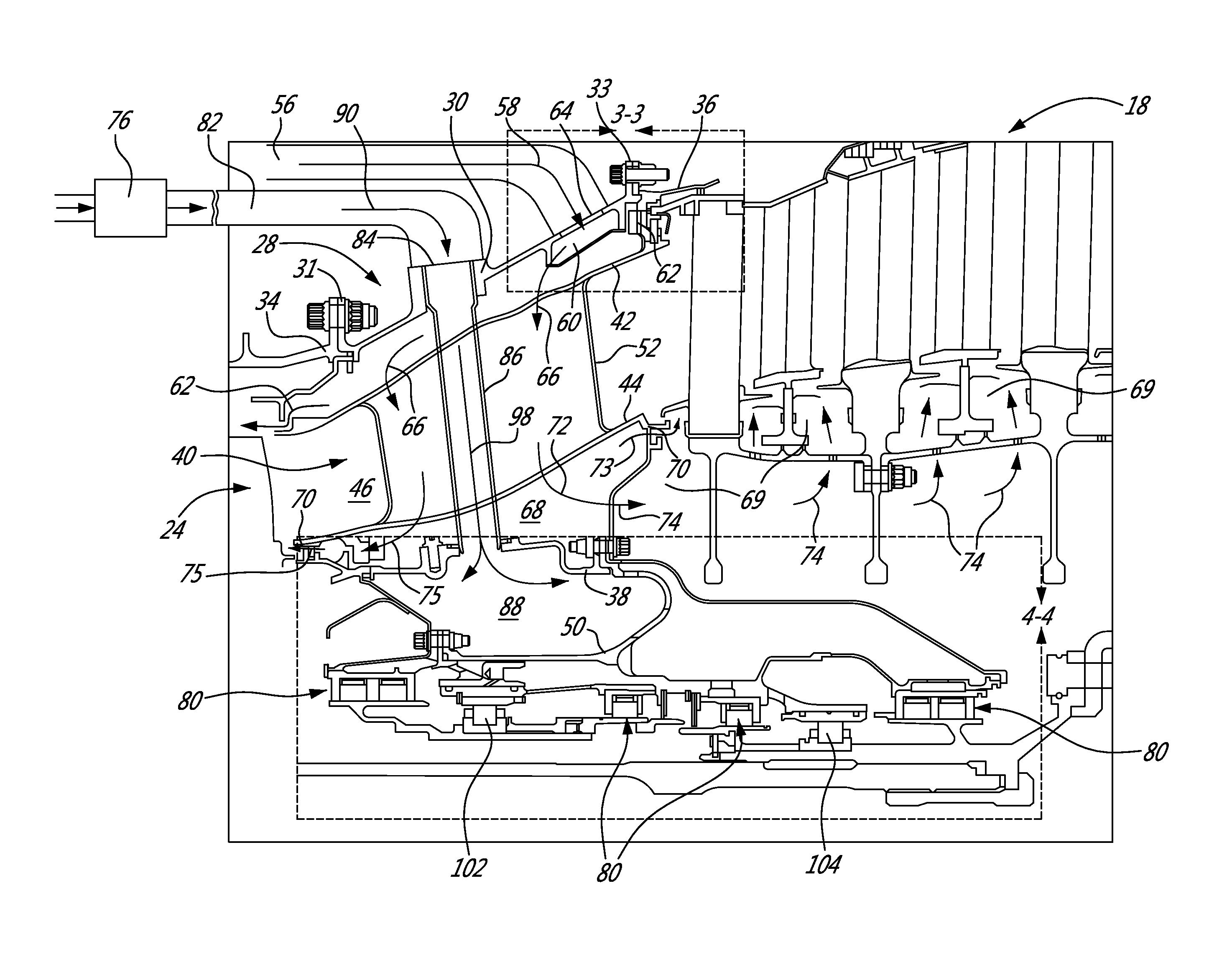
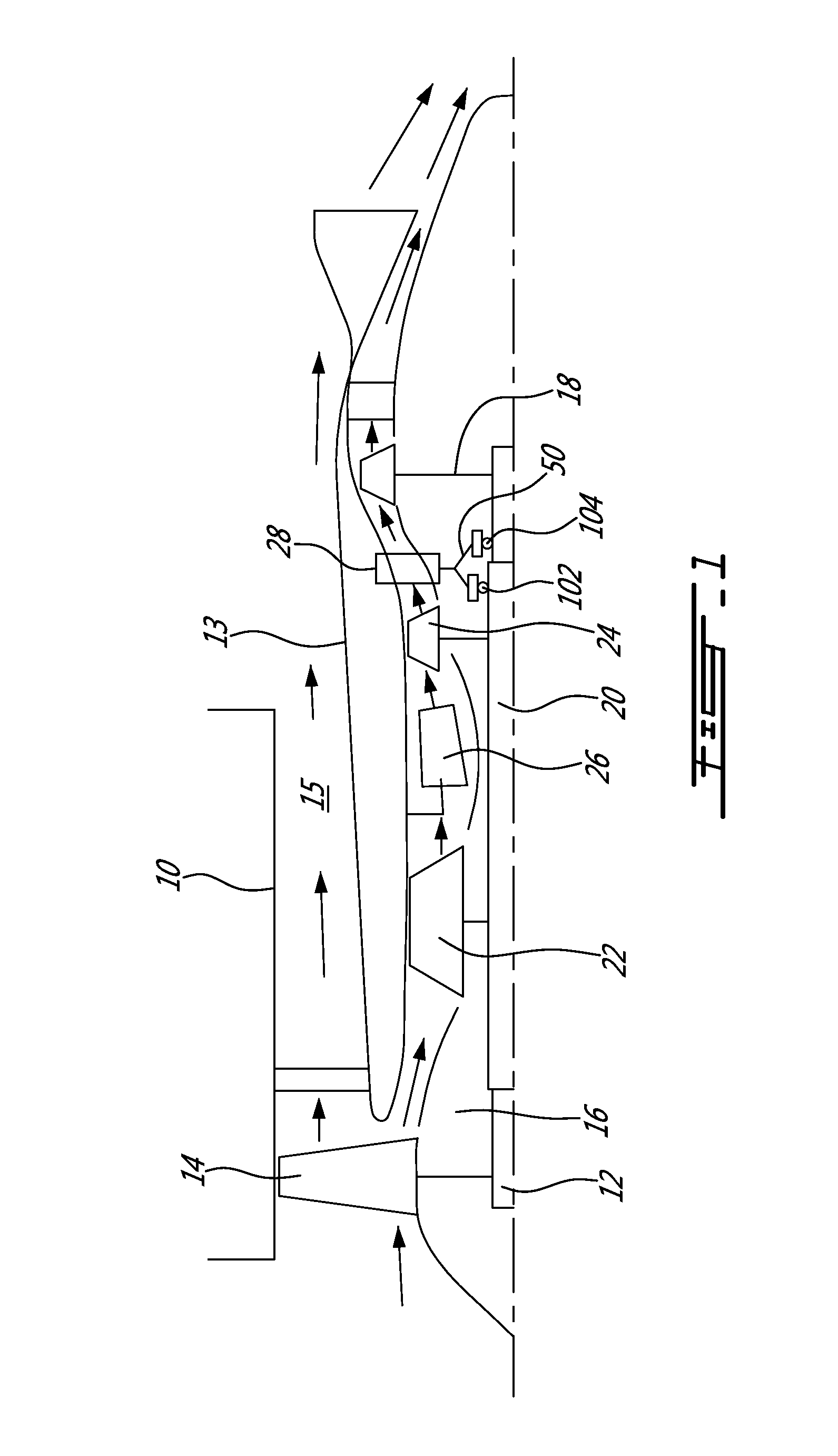
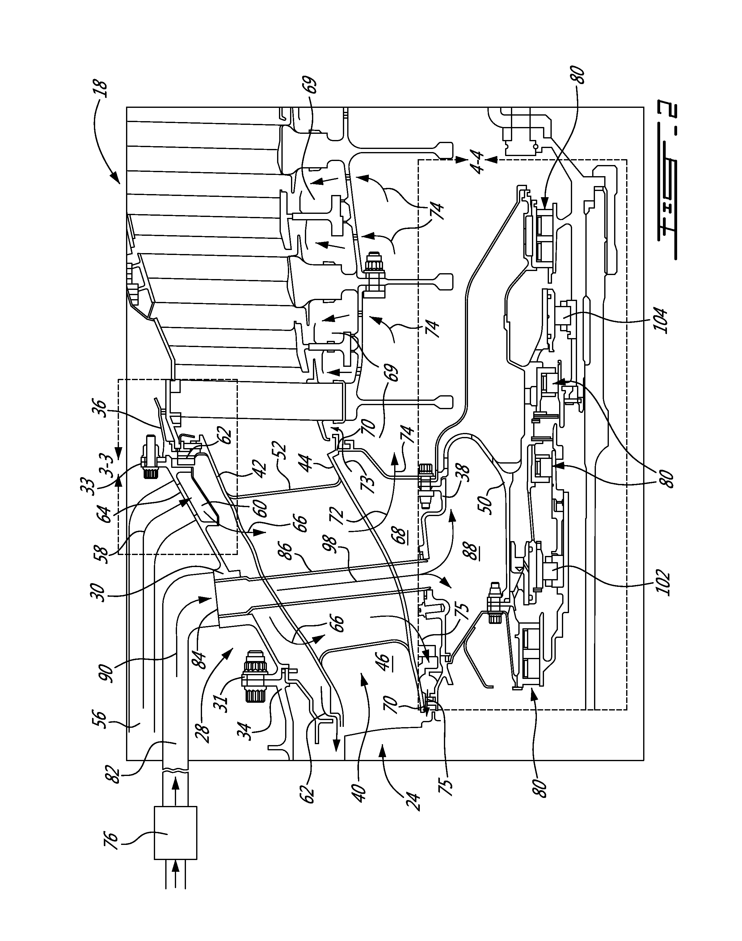
[0013]Referring to FIG. 1, an exemplary turbofan gas turbine engine includes a fan case 10, a core case 13, an air by-pass 15 between the fan case and the core case 13, a low pressure (LP) spool assembly which includes a fan assembly 14, a LP compressor assembly 16 and a LP turbine assembly 18 connected by a LP shaft 12, and a high pressure (HP) spool assembly which includes a HP compressor assembly 22 and a HP turbine assembly 24 connected by a HP shaft 20. The core casing 13 surrounds the low and high pressure spool assemblies to define a main fluid path therethrough. In the main fluid path, there is provided a combustor 26 to generate combustion gases to power the HP turbine assembly 24 and the LP turbine assembly 18. A mid-turbine frame assembly 28 is disposed between the HP turbine assembly 24 and the LP turbine assembly 18 and supports a bearing housing 50 containing for example #4 and #5 bearings 102 and 104 around the respective shafts 20 and 12. The terms “axial” and “radia...


PUM


Abstract

A mid-turbine frame is disposed between high and low pressure turbine assemblies. A secondary air system is defined in the mid-turbine frame (MTF) to provide cooling to the turbine section of the engine. The secondary air system may be used to cool and pressurize seals to assist with oil retention in bearing cavities. The temperature gain of the secondary air may be reduced by flowing the secondary air through one or more external lines and then generally radially inwardly through air passages defined in the MTF.

Description

CROSS-REFERENCE TO RELATED APPLICATIONS[0001]The present application claims priority on U.S. Provisional Application No. 61 / 537,764, filed on Sep. 22, 2011 the entire content of which is incorporated herein by reference.TECHNICAL FIELD[0002]The application relates generally to gas turbine engines and, more particularly, to an air system for a mid-turbine frame module of a gas turbine engine.BACKGROUND OF THE ART[0003]It is known to provide a mid-turbine frame assembly between high and low pressure turbine (HPT and LPT) rotor assemblies to support bearings and to transfer loads radially outwardly to a core engine casing. The mid-turbine frame assembly typically comprises a mid-turbine frame supporting an annular inter-turbine duct therein. The inter-turbine duct is defined between outer and inner duct walls which are interconnected by a plurality of radial hollow struts, thereby forming an annular hot gas path to convey the working fluid from the HPT to the LPT. The inter-turbine duc...

Claims


Application Information

Patent Timeline
Patent Type & Authority Patents(United States)
IPC IPC(8): F01D25/12F01D9/06F01D11/04
CPCF01D25/125F01D9/065F01D11/04Y02T50/675Y02T50/60
Inventor DUROCHER, ERICLEGARE, PIERRE-YVESCIAMPA, ALESSANDRO
Owner PRATT & WHITNEY CANADA CORP
Why Eureka
Try Eureka