Multiplatform GMTI radar with enhanced SNR, monopulse

a multi-platform, monopulse technology, applied in the field of radar processing systems, can solve the problems of limiting the gmti radar, the inability to distinguish slow-moving targets from background clutter, and the mdv is primarily limited, so as to increase the electrical size of the radar antenna aperture, reduce the mdv, and increase the effect of the effective electrical apertur

a multi-platform, monopulse technology, applied in the field of radar processing systems, can solve the problems of limiting the gmti radar, the inability to distinguish slow-moving targets from background clutter, and the mdv is primarily limited, so as to increase the electrical size of the radar antenna aperture, reduce the mdv, and increase the effect of the effective electrical apertur

US9285469B1Active Publication Date: 2016-03-15SRC INC

Image

  • Multiplatform GMTI radar with enhanced SNR, monopulse
  • Multiplatform GMTI radar with enhanced SNR, monopulse
  • Multiplatform GMTI radar with enhanced SNR, monopulse

Examples


Embodiment Construction

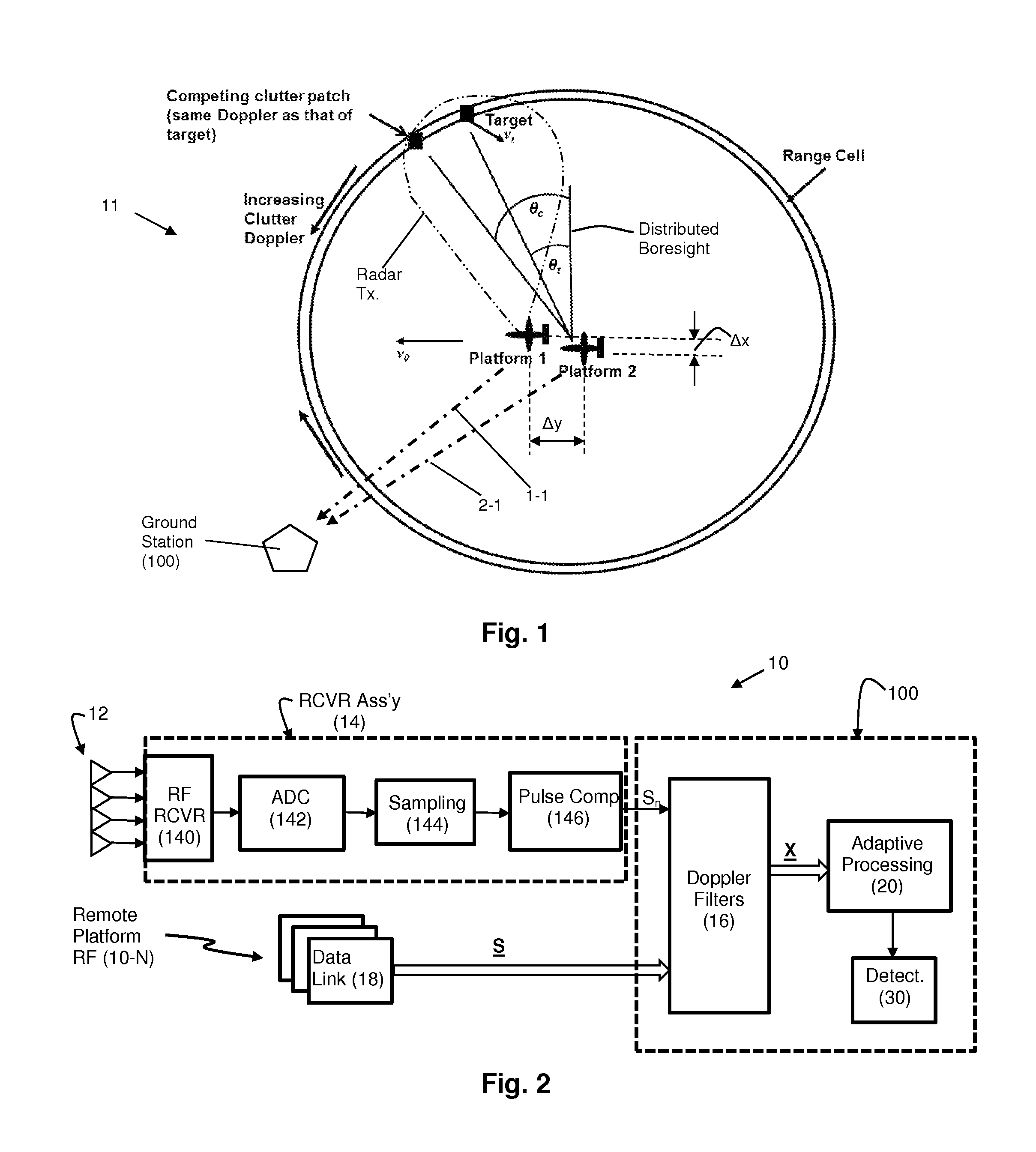
[0063]Reference will now be made in detail to the present exemplary embodiments of the invention, examples of which are illustrated in the accompanying drawings. Wherever possible, the same reference numbers will be used throughout the drawings to refer to the same or like parts. An exemplary embodiment of the system of the present invention is shown in FIG. 2, and is designated generally throughout by reference numeral 10.

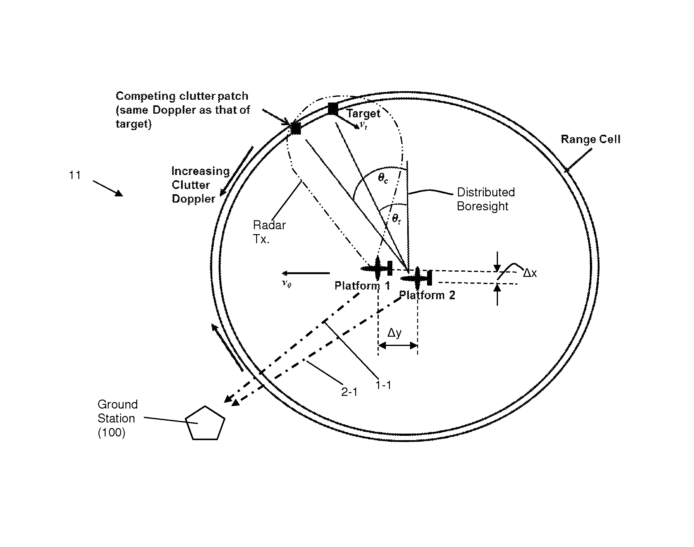
[0064]The present invention is directed to a ground moving target (GMTI) radar 10 that is configured to detect targets, including dismounts, with very small minimum detectable velocities by combining signals from antennas 12 on different spatially separated platforms (1, 2) in a main beam clutter-suppressing spatially adaptive process without requiring that the relative positions of the antenna phase centers be accurately tracked. The clutter nulling is in addition to that provided by the Doppler filters 16. The spatial displacement provides a narrow mainbeam clut...


PUM


Abstract

The present invention is directed to a ground moving target (GMTI) radar that can detect targets, including dismounts, with very small minimum detectable velocities by combining signals from antennas on different spatially separated platforms in a main beam clutter-suppressing spatially adaptive process without requiring that the relative positions of the antenna phase centers be accurately tracked. The clutter nulling is in addition to that provided by the Doppler filters. The spatial displacement provides a narrow mainbeam clutter null reducing undesired target suppression. The clutter-suppressing spatially adaptive structure is used in both the sum and delta channels of the monopulse processor so that the beam distortion caused by the spatial nulling is compensated for, and the monopulse look-up process is preserved to maintain angle accuracy. Noncoherent integration is employed to recover signal to noise loss resulting from the uncertain relative locations of the platforms.

Description

BACKGROUND OF THE INVENTION[0001]1. Field of the Invention[0002]The present invention relates generally to radar processing systems, and particularly to Ground Moving Target Indicator (GMTI) radar.[0003]2. Technical Background[0004]The term radar is an acronym that stands for “radio detection and ranging.” A radar system transmits radio frequency (RF) signals in a predetermined direction (i.e., a bearing) with the intention of contacting or illuminating moving or stationary objects, depending on the radar type, (“targets”). When the transmitted radar signal illuminates a target, a return signal is reflected back toward the radar receiver. The return signal is detected if it is stronger than the noise signals that may be present in the receiver. A target's bearing corresponds to the direction of the transmitted radar signal. Because the signal travels at the speed of light, the distance, or “range”, is determined by measuring the time between signal transmission and the reception of ...

Claims


Application Information

Patent Timeline
15 Mar 2016
Publication
US9285469B1
IPC
G01S13/44; G01S7/28; G01S7/00; G01S13/87; G01S13/524
CPC
G01S13/5248; G01S13/87; G01S13/5244; G01S13/44; G01S7/003; G01S7/2813; G01S13/4418; G01S13/4427
Inventors
SCHUMAN, HARVEY K.; THOMAS, JR., DANIEL D.