
Single-layer capacitive touch unit and capacitive touch screen

a capacitive touch and capacitive technology, applied in the field of single-layer capacitive touch units and capacitive touch screens, can solve the problems of limiting the yield rate and the impermanent issue of touch signal noise ratio, so as to increase the capacitance of the mutual capacitance, and increase the snr of the touch signal

Active Publication Date: 2016-03-15
TCL CHINA STAR OPTOELECTRONICS TECH CO LTD
View PDF7 Cites 3 Cited by
  • Summary
  • Abstract
  • Description
  • Claims
  • Application Information

AI Technical Summary

Benefits of technology

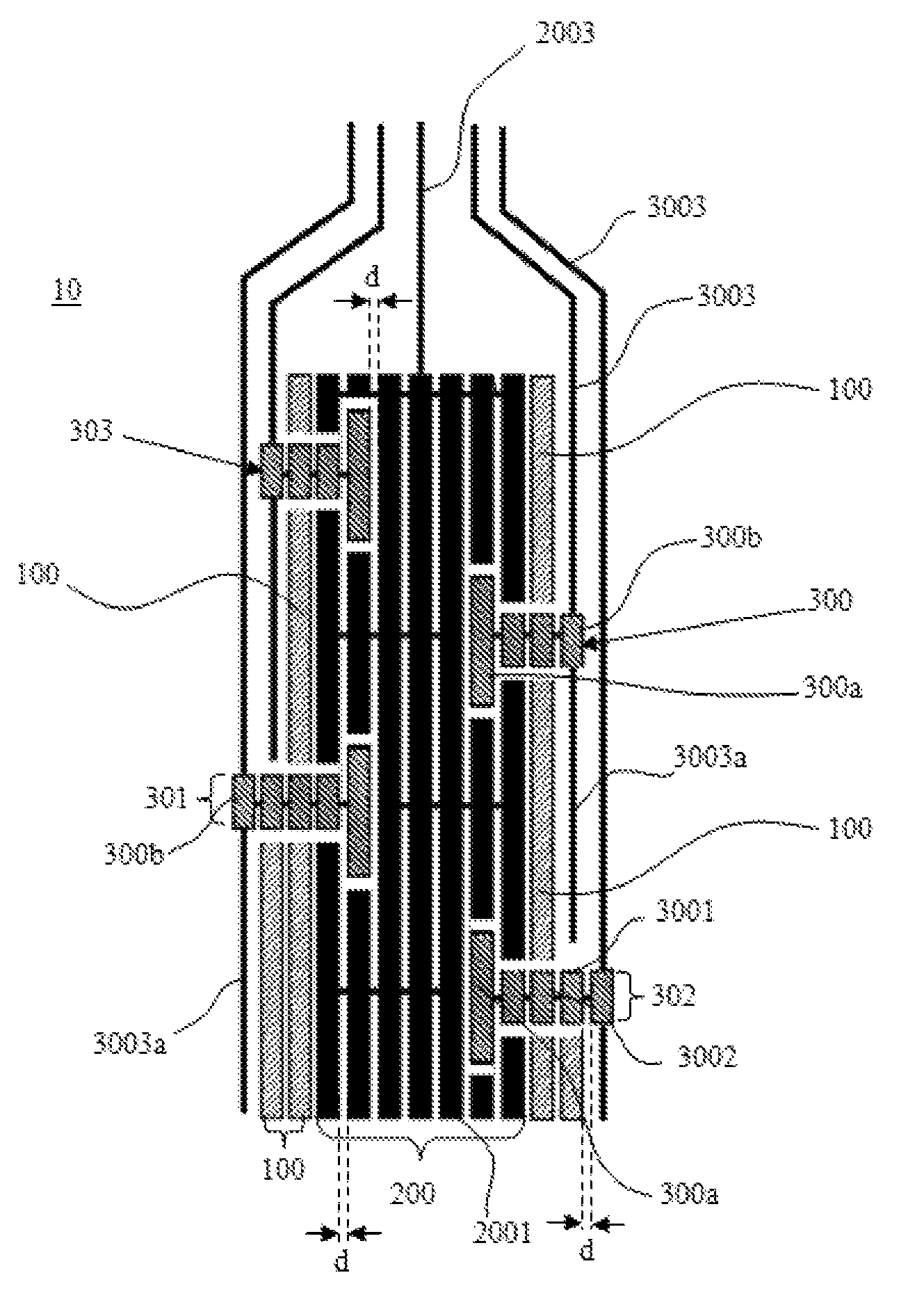
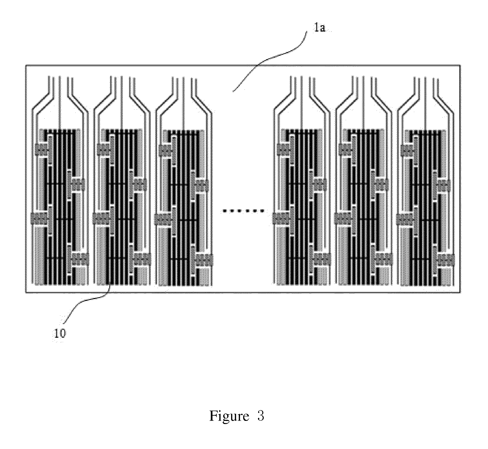
The present invention provides a single-layer capacitive touch screen that can improve the signal-noise-ratio (SNR) of touch signals by reducing the effect of noise signals. This is achieved by extending the end of the scan electrode lead connected to the scan electrode to near the next electrode and forming extending lead for shielding the signal between them. Additionally, a filling metal is placed between the sensing electrode and scan electrode lead to further shield interference. The scan electrode is embedded in the sensing electrode, which increases the capacitance of the mutual capacitance between the two electrodes and increases the SNR of the touch signal. The invention also divides the sensing electrode and scan electrode into identical units that are coplanar and have the same arrangement direction to reduce visual perceptibility to human eye and solve the visual difference between the sensing electrode and scan electrode array. Overall, this innovation enhances the accuracy and reliability of touch screen technology.

Problems solved by technology

This approach requires complex manufacturing process and the yield rate is restricted by the manufacturing process.
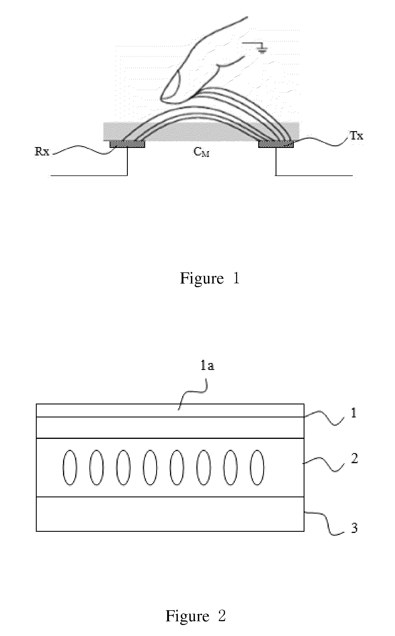
Because the sensing electrodes Rx, scanning electrode array Tx and corresponding connection wires are all disposed on the same plane, how to reduce the effect of noise signal on the touch signal and improve the touch signal-noise-ratio (SNR) becomes an imperative issue.

Method used


Image

  • Single-layer capacitive touch unit and capacitive touch screen
  • Single-layer capacitive touch unit and capacitive touch screen
  • Single-layer capacitive touch unit and capacitive touch screen

Examples


Embodiment Construction

[0030]As aforementioned, the present invention is to provide a single-layer capacitive touch unit able to reduce the effect of noise signal on the touch signal and improve the SNR of the touch signal, and a capacitive touch screen comprising the single-layer capacitive touch unit. The single-layer capacitive touch unit comprises: a sensing electrode, connected to a control unit through a sensing electrode lead; and a plurality of scan electrodes, disposed at two sides of the sensing electrode; the scan electrode being connected to the control unit through a scan electrode lead, and the scan electrodes and the sensing electrode being coplanar; wherein one end of the scan electrode lead being connected to a second end of the scan electrode and extending to near a next scan electrode to form extending lead; and the other end of the scan electrode lead being connected to the control unit.

[0031]In the aforementioned capacitive touch unit, the end of the scan electrode lead connected to t...


PUM

PropertyMeasurementUnit
lengthaaaaaaaaaa
shapeaaaaaaaaaa
transparentaaaaaaaaaa

Abstract

The invention discloses a single-layer capacitive touch unit, including a sensing electrode, connected to a control unit through a sensing electrode lead; and a plurality of scan electrodes, disposed at two sides of the sensing electrode; the scan electrode being connected to the control unit through a scan electrode lead, and the scan electrodes and the sensing electrode being coplanar; wherein one end of scan electrode lead connected to a second end of scan electrode and extending to near a next scan electrode to form extending lead; and the other end of scan electrode lead connected to the control unit. The invention also provides a capacitive touch screen with the capacitive touch unit. The invention can reduce the effect of noise signal on the touch signal and increase SNR of the touch signal.

Description

BACKGROUND OF THE INVENTION[0001]1. Field of the Invention[0002]The present invention relates to the field of touch techniques, and in particular to a single-layer capacitive touch unit and a capacitive touch screen with capacitive touch unit.[0003]2. The Related Arts[0004]The touch display screen as an input medium is one of the simplest and most convenient modes for human-machine dialogue. Hence, the touch display screen is widely applied to various electronic products. Based on the operating theory and information transmission medium, the touch screen products care categorized into four types: infrared touch screen, capacitive touch screen, resistive touch screen and surface acoustic wave touch screen, wherein the capacitive touch screen becomes the main stream technology for touch screen due to the advantages of long life-span, high transmittance and supporting multi-touch.[0005]The capacitive touch screens include the surface capacitive type and the projected capacitive type. T...

Claims


Application Information

Patent Timeline
Patent Type & Authority Patents(United States)
IPC IPC(8): G02F1/1333G06F3/041G06F3/044
CPCG02F1/13338G06F3/044G06F3/0412G06F2203/04107G06F3/04164G06F3/0443
Inventor QIU, JIELIN, YUNG-LUN
Owner TCL CHINA STAR OPTOELECTRONICS TECH CO LTD
Learn More