
Image sequence enhancement and motion picture project management system

a motion picture and project management system technology, applied in the field of image analysis and image enhancement, can solve the problems of large labor intensity, system not using the underlying luminance gray scale of objects in images, and the inability to automatically adjust the position and shape of the mask to correspond with image feature displacement and distortion from one frame to another, etc., to achieve the effect of rapid conversion of a sequence of images

Inactive Publication Date: 2016-03-15
LEGEND FILMS INC
View PDF416 Cites 4 Cited by
  • Summary
  • Abstract
  • Description
  • Claims
  • Application Information

AI Technical Summary

Benefits of technology

[0013]Embodiments of the invention generally are directed at image analysis and image enhancement and enable the rapid conversion of a sequence of images as well as project management related to the production, processing or conversion of motion pictures. Large motion picture projects generally utilize workers of several roles to process each image that makes up a motion picture, which may number in the hundreds of thousands of image frames. One or more embodiments of the invention enables a computer and database to be configured to accept the assignment of tasks related to artists, time entries for tasks by artists and review of time and actuals of artists by coordinators, a.k.a., “production” and the review of work product by editorial roles. The system thus enables artists working on shots made up of multiple images to be managed for successful on-budget completion of projects, along with minimization of generally vast storage requirements for motion picture assets and enable prediction of costs for future bidding on projects given quality, ratings of workers to use and schedule.
[0025]1. Automatic mask fitting using Fast Fourier Transform and Gradient Decent Calculations based on luminance and pattern matching which references the same masked area of the key frame followed by all prior subsequent frames in succession. Since the computer system implementing embodiments of the invention can reshape at least the outlines of masks from frame to frame, large amounts of labor can be saved from this process that traditionally has been done by hand. In 2D to 3D conversion projects, sub-masks can be adjusted manually within a region of interest when a human recognizable object rotates for example, and this process can be “tweened” such that the computer system automatically adjusts sub-masks from frame to frame between key frames to save additional labor.
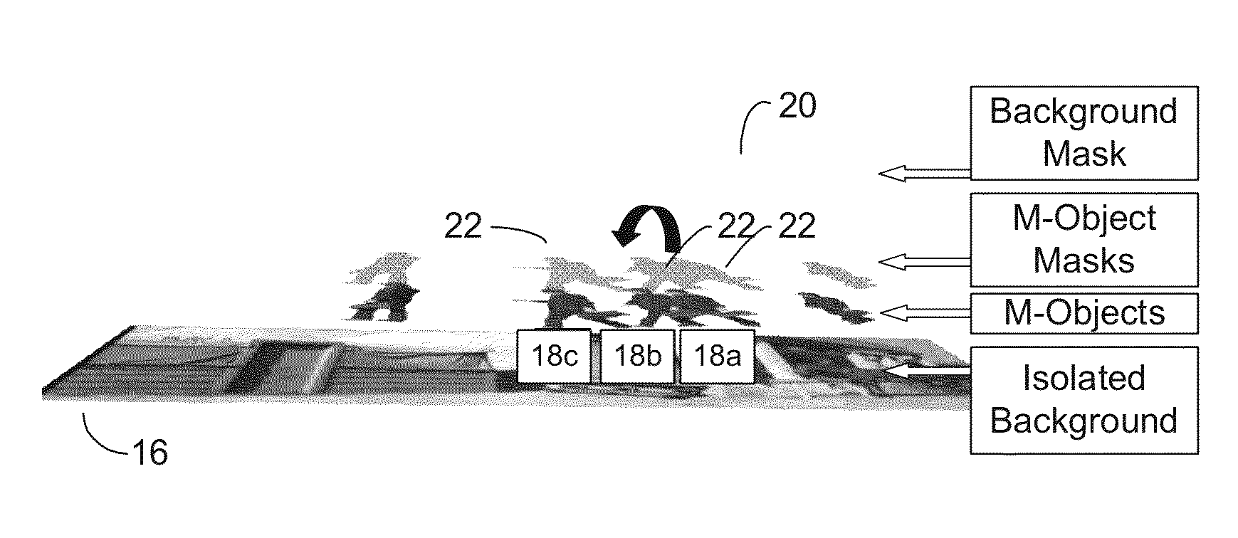
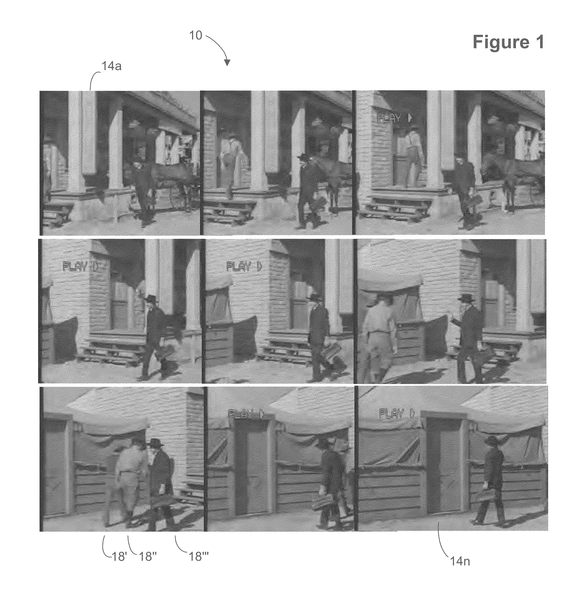
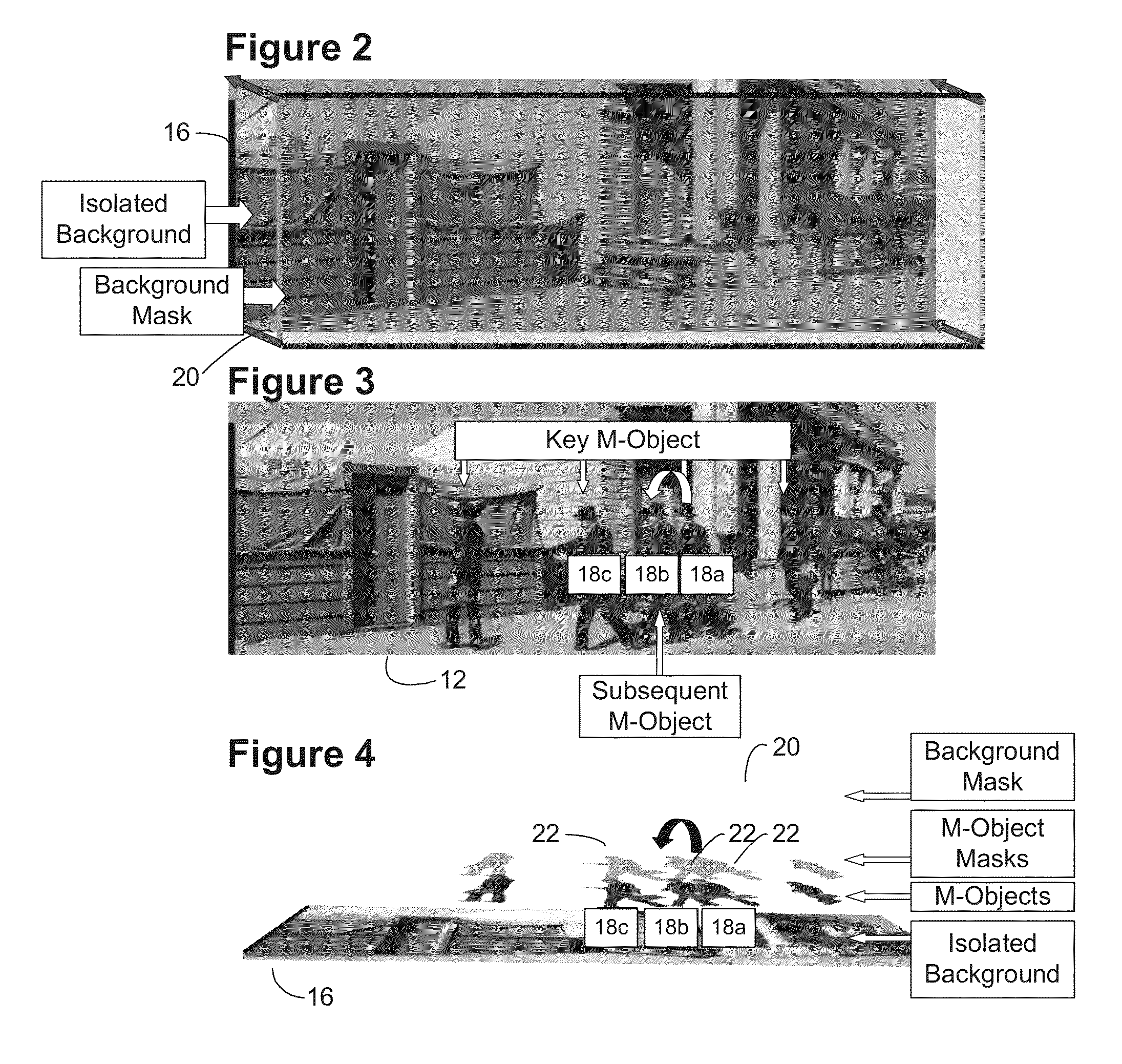
[0031]For colorization projects, the single background image representing the series of camera pan images is color designed using multiple color transform look up tables limited only by the number of pixels in the display. This allows the designer to include as much detail as desired including air brushing of mask information and other mask application techniques that provide maximum creative expression. For depth conversion projects, (i.e., two-dimensional to three-dimensional movie conversion for example), the single background image representing the series of camera pan images may be utilized to set depths of the various items in the background. Once the background color / depth design is completed the mask information is transferred automatically to all the frames that were used to create the single composited image. In this manner, color or depth is performed once per multiple images and / or scene instead of once per frame, with color / depth information automatically spread to individual frames via embodiments of the invention. Masks from colorization projects may be combined or grouped for depth conversion projects since the colorization masks may contain more sub-areas than a depth conversion mask. For example, for a coloration project, a person's face may have several masks applied to areas such as lips, eyes, hair, while a depth conversion project may only require an outline of the person's head or an outline of a person's nose, or a few geometric shape sub-masks to which to apply depth. Masks from a colorization project can be utilized as a starting point for a depth conversion project since defining the outlines of human recognizable objects by itself is time consuming and can be utilized to start the depth conversion masking process to save time. Any computer-generated elements at the background level may be applied to the single background image.
[0034]Static Camera Scenes With and Without Film Weave, Minor Camera Following and Camera Drift: In scenes where there is minor camera movement or film weave resulting from the sprocket transfer from 35 mm or 16 mm film to digital format, the motion objects are first fully masked using the techniques listed above. All frames in the scene are then processed automatically to create a single image that represents both the static foreground elements and background elements, eliminating all masked moving objects where they both occlude and expose the background.
[0037]One or more tools employed by the system enable real-time editing of 3D images without re-rendering for example to alter layers / colors / masks and / or remove artifacts and to minimize or eliminate iterative workflow paths back through different workgroups by generating translation files that can be utilized as portable pixel-wise editing files. For example, a mask group takes source images and creates masks for items, areas or human recognizable objects in each frame of a sequence of images that make up a movie. The depth augmentation group applies depths, and for example shapes, to the masks created by the mask group. When rendering an image pair, left and right viewpoint images and left and right translation files may be generated by one or more embodiments of the invention. The left and right viewpoint images allow 3D viewing of the original 2D image. The translation files specify the pixel offsets for each source pixel in the original 2D image, for example in the form of UV or U maps. These files are generally related to an alpha mask for each layer, for example a layer for an actress, a layer for a door, a layer for a background, etc. These translation files, or maps are passed from the depth augmentation group that renders 3D images, to the quality assurance workgroup. This allows the quality assurance workgroup (or other workgroup such as the depth augmentation group) to perform real-time editing of 3D images without re-rendering for example to alter layers / colors / masks and / or remove artifacts such as masking errors without delays associated with processing time / re-rendering and / or iterative workflow that requires such re-rendering or sending the masks back to the mask group for rework, wherein the mask group may be in a third world country with unskilled labor on the other side of the globe. In addition, when rendering the left and right images, i.e., 3D images, the Z depth of regions within the image, such as actors for example, may also be passed along with the alpha mask to the quality assurance group, who may then adjust depth as well without re-rendering with the original rendering software. This may be performed for example with generated missing background data from any layer so as to allow “downstream” real-time editing without re-rendering or ray-tracing for example. Quality assurance may give feedback to the masking group or depth augmentation group for individuals so that these individuals may be instructed to produce work product as desired for the given project, without waiting for, or requiring the upstream groups to rework anything for the current project. This allows for feedback yet eliminates iterative delays involved with sending work product back for rework and the associated delay for waiting for the reworked work product. Elimination of iterations such as this provide a huge savings in wall-time, or end-to-end time that a conversion project takes, thereby increasing profits and minimizing the workforce needed to implement the workflow.
[0039]Regardless of the type of project work performed on a given asset, the asset is reviewed for example using an interface that couples with the project management database to enable the viewing of work product. Generally, editorial role based users use the interface most, artists and stereographers less and lead artists the least. The review notes and images may be viewed simultaneously, for example with a clear background surrounding text that is overlaid on the image or scene to enable rapid review and feedback by a given worker having a particular role. Other improvements to the project management database include ratings or artists and difficulty of the asset. These fields enable workers to be rated and projected costs to be forecast when bidding projects, which is unknown in the field of motion picture project planning.

Problems solved by technology

In these prior inventions the mask information does not contain any information specific to the underlying luminance gray scale and therefore no automatic position and shape correction of the mask to correspond with image feature displacement and distortion from one frame to another is possible.
The creation of wire frame models is a large undertaking in terms of labor.
These systems also do not utilize the underlying luminance gray scale of objects in the images to automatically position and correct the shape of the masks of the objects to correspond with image feature displacement and distortion from one frame to another.
Hence, great amounts of labor are required to manually shape and reshape masks for applying depth or Z-dimension data to the objects.
Motion objects that move from frame to frame thus require a great deal of human intervention.
In addition, there are no known solutions for enhancing two-dimensional images into three-dimensional images that utilize composite backgrounds of multiple images in a frame for spreading depth information to background and masked objects.
In other words, known systems gap fill using algorithms for inserting image data where none exists, which causes artifacts.
There are no known current methods that obtain and make use of metadata associated with the computer-generated elements for a movie to be converted.
This is the case since studios that own the older 2D movies may not have retained intermediate data for a movie, i.e., the metadata associated with computer generated elements, since the amount of data in the past was so large that the studios would only retain the final movie data with rendered computer graphics elements and discard the metadata.
With hundreds of thousands of frames in a movie, the amount of time that it takes to iterate back through frames containing artifacts can become high, causing delays in the overall project.
Even if the re-rendering process takes place locally, the amount of time to re-render or ray-trace all of the images of a scene can cause significant processing and hence delays on the order of at least hours.
As described above, industrial based motion picture projects typically include hundreds of thousands of frames, however in addition, these types of projects may also utilize use gigantic amounts of storage including potentially hundreds of layers of masks and images per frame and hundreds of workers.
In addition, project management tools utilized include off the shelf project management tools that are not tailored for the specifics of project management in a unique vertical industry such as motion picture effects and conversion projects.
Hence, predicting costs and quality and repeatedly performing projects in the film industry has been difficult to accomplish to date.
Although standalone tools exist to perform these tasks, they are generally not integrated and are difficult for personnel in different roles to utilize.
Regardless of the known techniques, there are no known optimizations or implementations of project management solutions that take into account the unique requirements of the motion picture industry.

Method used


Image

  • Image sequence enhancement and motion picture project management system
  • Image sequence enhancement and motion picture project management system
  • Image sequence enhancement and motion picture project management system

Examples


Embodiment Construction

[0171]FIG. 97 illustrates and architectural view of an embodiment of the invention. One or more embodiments of the system include computer 9702 and database 9701 coupled with computer 9702. Any computer architecture having any number of computers, for example coupled via a computer communication network is in keeping with the spirit of the invention. Database 9701 coupled with computer 9702 includes at least a project table, shot table, task table and timesheet table. The project table generally includes project identifier and description of a project related to a motion picture. The shot table generally includes a shot identifier and references a plurality of images with a starting frame value and an ending frame value wherein the plurality of images are associated with the motion picture that is associated with the project. The shot table generally includes at least one shot having status related to progress of work performed on the shot. The task table generally references the pr...


PUM

PropertyMeasurementUnit
depthaaaaaaaaaa
depthaaaaaaaaaa
thresholdaaaaaaaaaa

Abstract

The system enables conversion of black and white images to color images and / or two-dimensional images into three-dimensional images based on adding color and / or depth to images using masks for regions in the images, as well as reshaping of masks to cover objects that have moved and changed shape as the objects move in a sequence of images. Also, includes motion picture project management system for reviewers, coordinators and artists. Artists utilize image analysis and image enhancement and computer graphics processing for example to convert two-dimensional images into three-dimensional images or otherwise create or alter motion pictures. Enables the efficient management of projects related to motion pictures to enable enterprises to manage assets, control costs, predict budgets and profit margins, reduce archival storage and otherwise provide displays tailored to specific roles to increase worker efficiency.

Description

[0001]This application is a continuation in part of U.S. Utility patent application Ser. No. 13 / 366,899, issued as U.S. Pat. No. 9,031,383, filed 6 Feb. 2012, which is a continuation in part of U.S. Utility patent application Ser. No. 13 / 029,862, issued as U.S. Pat. No. 8,385,684, filed 17 Feb. 2011, which is a continuation in part of U.S. Utility patent application Ser. No. 12 / 976,970, issued as U.S. Pat. No. 8,401,336, filed 22 Dec. 2010, which is a continuation in part of U.S. Utility patent application Ser. No. 12 / 913,614, issued as U.S. Pat. No. 8,396,328, filed 27 Oct. 2010, which is a continuation in part of U.S. Utility patent application Ser. No. 12 / 542,498, issued as U.S. Pat. No. 7,907,793, filed 17 Aug. 2009, which is a continuation in part of U.S. Utility patent application Ser. No. 12 / 032,969, filed 18 Feb. 2008 and issued as U.S. Pat. No. 7,577,312, which is a continuation of U.S. Utility patent application Ser. No. 11 / 324,815, issued as U.S. Pat. No. 7,333,670, filed...

Claims


Application Information

Patent Timeline
Patent Type & Authority Patents(United States)
IPC IPC(8): H04N5/93H04N13/02G11B27/031
CPCG11B27/031H04N13/026H04N13/0257H04N13/0267H04N13/257H04N13/261H04N13/266
Inventor SANDREW, BARRYBALDRIDGE, TONYSANDREW, JAREDLOPEZ, ANTHONY
Owner LEGEND FILMS INC
Learn More