Electric motor control device
a technology of electric motors and control devices, applied in the direction of electric generator control, dynamo-electric converter control, dynamo-electric gear control, etc., to achieve the effect of reducing vibration further, reducing vibration further, and reducing the difficulty of calculation of estimated corrected rotation speed
- Summary
- Abstract
- Description
- Claims
- Application Information
AI Technical Summary
Benefits of technology
Problems solved by technology
Method used
Image
Examples
embodiment 1
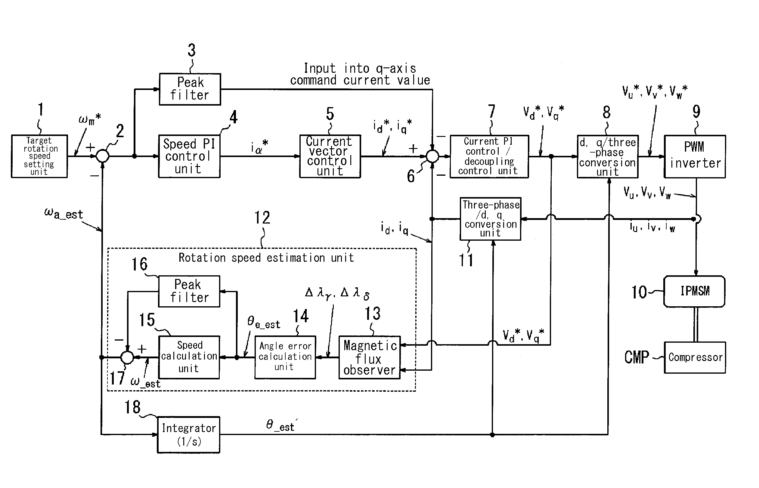
[0044]First, the overall structure of an electric motor control device according to Embodiment 1 of the present invention is described.
[0045]By performing position sensorless control, the electric motor control device of Embodiment 1 controls an Interior Permanent Magnet Synchronous Motor (IPMSM) that drives the compressor in an automobile air conditioner.
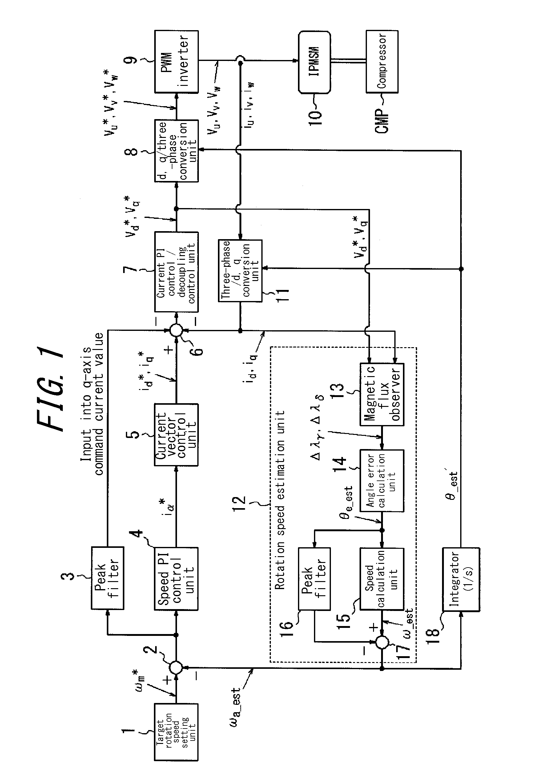
[0046]As illustrated in FIG. 1, the electric motor control device of Embodiment 1 includes a target rotation speed setting unit 1, a subtractor 2, a peak filter 3, a speed PI (proportional and integral) control unit 4, a current vector control unit 5, a subtractor 6, a current PI control / decoupling control unit 7, a d, q / three-phase conversion unit 8, and a Pulse Width Modulation (PWM) inverter 9. The PWM inverter 9 is connected to an IPMSM 10.
[0047]The output shaft of the IPMSM 10 is connected to a vane compressor CMP for an air conditioner, and the IPMSM 10 can drive the compressor CMP.
[0048]The electric motor control device of E...
embodiment 2
[0116]Next, Embodiment 2 is described. In the description of Embodiment 2, structural components similar to Embodiment 1 are not illustrated or are labeled with the same reference signs, and a description thereof is omitted. Only the differences are described.
[0117]The overall structure of an electric motor control device according to Embodiment 2 of the present invention is described based on the attached drawings.
[0118]The electric motor control device of Embodiment 2 differs from Embodiment 1 by not including the peak filter 3 of Embodiment 1, by the addition of a phase lead compensator 22, and by a resulting change to the subtractor 6.
[0119]In Embodiment 2, as illustrated in FIG. 8, a signal adjusted for phase and amplitude with respect to the rotation speed estimated value correction amount calculated in the peak filter 16 is used instead of the signal calculated by the peak filter 3 in Embodiment 1. The values calculated by the peak filters 16 and 3 are both signals generated ...
PUM
 Abstract
Description
Claims
Application Information
 - R&D
- Intellectual Property
- Life Sciences
- Materials
- Tech Scout
- Unparalleled Data Quality
- Higher Quality Content
- 60% Fewer Hallucinations
Browse by: Latest US Patents, China's latest patents, Technical Efficacy Thesaurus, Application Domain, Technology Topic, Popular Technical Reports.
© 2025 PatSnap. All rights reserved.Legal|Privacy policy|Modern Slavery Act Transparency Statement|Sitemap|About US| Contact US: help@patsnap.com


