Electric riding mower having air-cooled chassis and pivotable protective cowling

a technology of electric riding mowers and chassis, which is applied in the direction of electric devices, battery/fuel cell control arrangements, electric devices, etc., can solve the problems of reducing the size of electronic devices controlling batteries and motors, inhibiting normal operation of electronic circuits, and so as to achieve efficient cooling, increase heat, and improve the effect of reducing the size of electronic devices

Inactive Publication Date: 2016-03-22
YANMAR CO LTD
View PDF80 Cites 13 Cited by
  • Summary
  • Abstract
  • Description
  • Claims
  • Application Information

AI Technical Summary

Benefits of technology

[0026]An electric riding mower according to the present invention includes two running motors independently driving paired driving wheels; a mower blade mowing grass by being rotated; a mowing motor rotating the mower blade; a battery supplying electric power to the running motors and the mowing motor; and a mower-motor driver controlling the rotational speed of the mowing motor, wherein the mower-motor driver is disposed in a driver storage part on a front part of the mower, and an air intake part taking in external air is disposed on a front surface of the driver storage part. Thus, as the electric riding mower runs, external air can be effectively taken in to the driver storage part through the air intake part. In this way, the motor driver can be efficiently cooled. Thus, increased heat due to size reduction and integration of the motor driver can be efficiently cooled. Hence, an electric riding mower that has a simple configuration and efficiently cools a motor driver can be provided.
[0027]By providing a screen for preventing intrusion of scattered objects on the air intake part, grass mowed by the mower blade is prevented from scattering and entering through the air intake part. In this way, operational failures due to scattered objects attaching to the mower-motor driver can be prevented.
[0028]By providing a fan disposed behind and adjacently to the air intake part and for supporting intake of external air, the mower-motor driver can be cooled even more efficiently.
[0029]The electric riding mower may further include a pair of left and right chassis, wherein the driver storage part may be interposed between the chassis, and front end parts of the chassis may be inclined forward and upward. In this way, the total length of the electric riding mower may be reduced while disposing the driver storage part between the paired chassis. By reducing the total length of the electric riding mower, the wheel space can be reduced, enabling turning with a small radius. In this way, the operability of the electric riding mower is improved.
[0030]An operator's seat, a cowling covering the chassis from above, and a step configured to place feet of an operator seated in the operator's seat and configured as part of the cowling may be provided, and a front end part of the step may be inclined forward and upward along the chassis. In this way, the upper surface of the front end part of the step is disposed with an inclination toward the operator's seat. In this way, the operator can comfortably place his or her feet on the front end part of the step, and comfort of operation can be improved.
[0031]If the air intake part is a slit, intrusion of scattered objects through the air intake part may be effectively prevented while effectively taking in external air.

Problems solved by technology

For electric vehicles, in addition to reduction in the battery size and motor size, size reduction in the electronic devices controlling the batteries and motors is a technical problem.
There are other problems in reducing the size of electronic devices.
An increase in the electronic circuit density per unit area causes an increase in the amount of heat generation (current flowing through the circuit) per unit area of the electronic circuit, and thus there is a problem in that normal operation of the electronic circuit is inhibited due to an increase in the amount of heat generation.
Hence, size reduction of electronic devices and cooling of such electronic devices are problems that must be solve simultaneously.

Method used


Image

  • Electric riding mower having air-cooled chassis and pivotable protective cowling
  • Electric riding mower having air-cooled chassis and pivotable protective cowling
  • Electric riding mower having air-cooled chassis and pivotable protective cowling

Examples


Embodiment Construction

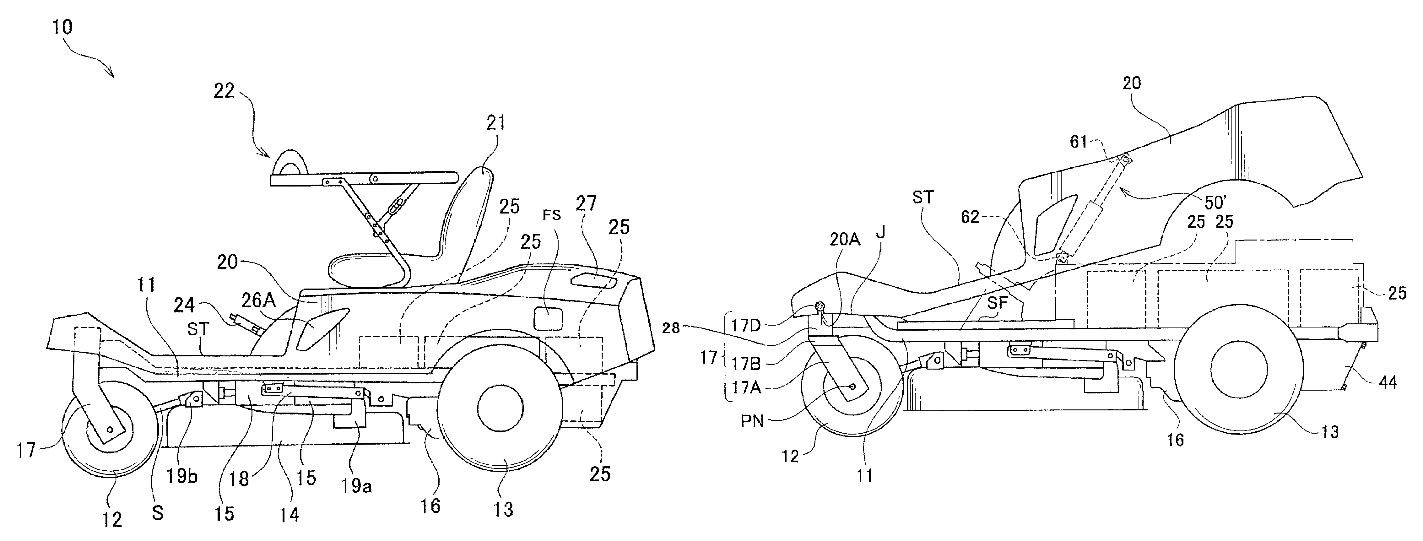
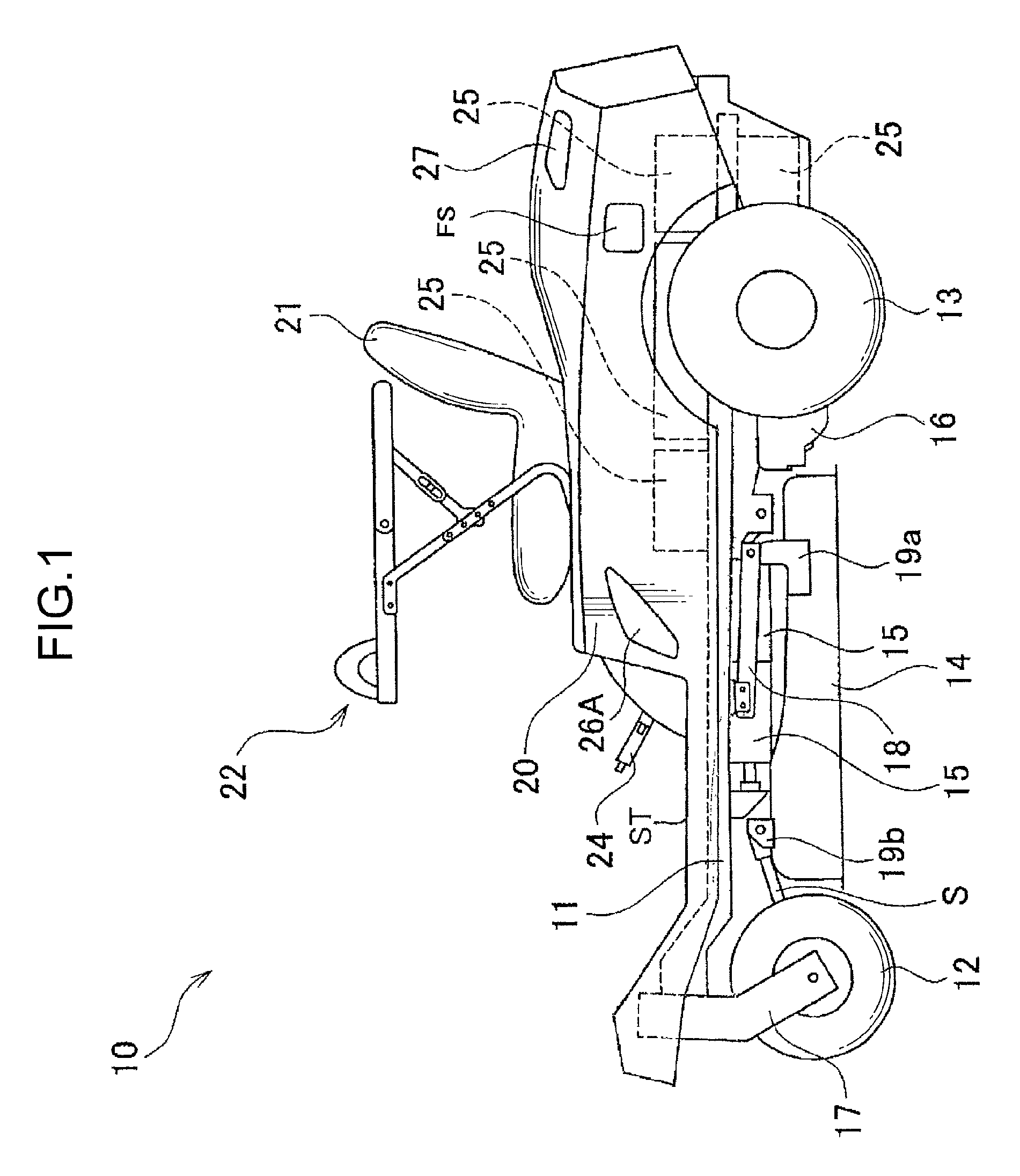
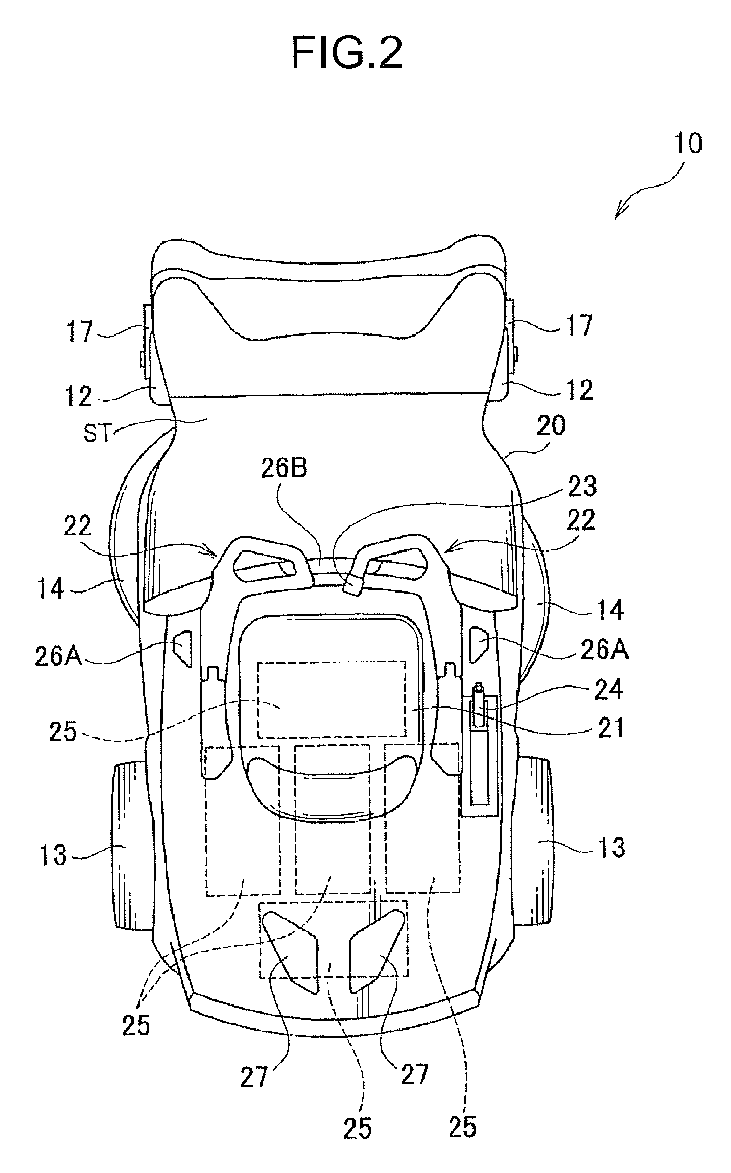
[0078]Preferred embodiments of the present invention will be described in detail below with reference to the drawings. FIGS. 1 and 2 respectively illustrate a plan view and a side view of an electric lawnmower 10, which is an example of an electric riding mower according to the present invention. The electric lawnmower 10 includes a pair of frame-like chassis 11 disposed on the left and right sides, a pair of front tires (front wheels) 12 and a pair of rear tires (rear wheels) 13 disposed below the chassis 11. A mower deck 14 is disposed between the front tires 12 and the rear tires 13. The mower deck 14 is shaped like a substantially oval plate with a rim and is disposed with the bottom surface of the plate facing upward. Two mower blades (mowing blades) (not shown) are disposed side by side along the major axis on the inner side of the mower deck 14. Mowing motors 15 and 15 are attached to the centers of rotation of the mower blades. The mower deck 14 is disposed with the minor ax...


PUM


Abstract

An electric riding mower efficiently cools a motor driver. The mower includes two running motors 16 independently driving paired rear tires 13; a mower blade mowing grass by being rotated; a mowing motor 15 rotating the mower blade; a battery 25 supplying electric power to the running motors 16 and the mowing motor 15; and a mower-motor driver MD controlling the rotational speed of the mowing motor 15, wherein the mower-motor driver MD is disposed in a driver storage part on a front part of the mower, and a slit 33SL taking in external air is disposed on a front surface of the driver storage part.

Description

TECHNICAL FIELD[0001]The present invention relates to an electric riding mower including two running motors independently driving paired driving wheels, a mower blade mowing grass by being rotated, a mowing motor rotating the mower blade, and a battery supplying electric power to the running motors and the mowing motor.BACKGROUND ART[0002]Recently, there has been a social movement of restricting exhaust gases, including greenhouse gases, from the perspective of global warming prevention. The response to such a movement has been especially notable in the automobile industry, and the development of so-called eco-cars, such as hybrid cars and electric vehicles, has been promoted. In particular, there has been an active technological development in commercializing electric vehicles using batteries as power sources.[0003]For electric vehicles, in addition to reduction in the battery size and motor size, size reduction in the electronic devices controlling the batteries and motors is a te...

Claims


Application Information

Patent Timeline
Patent Type & Authority Patents(United States)
IPC IPC(8): A01D69/00B60L11/18A01D67/00B60L3/04B60L3/00B60L1/00A01D69/02
CPCA01D69/02A01D67/00B60L1/003B60L3/0046B60L3/04B60L11/1803B60L11/1816B60L11/1866Y02T90/14B60L2200/22B60L2220/42B60L2220/44B60L2240/421B60L2250/16Y02T10/648Y02T10/7005Y02T10/7061Y02T10/7072B60L53/14B60L50/51B60L58/22B60L58/15B60L58/10Y02T10/64Y02T10/70
Inventor MORIGUCHI, KAZUMAMOTEGI, SHINICHIMATSUMOTO, KEIJINAKAGAKI, MITSUHIROEBIHARA, TOMOYUKI
Owner YANMAR CO LTD
Why Eureka
Try Eureka