
Spray dryer absorber vibrator device and method

a technology of absorber and dryer, which is applied in the direction of emission prevention, separation processes, lighting and heating apparatus, etc., can solve the problems of loosening and dislocation, and achieve the effect of less time and expens

Active Publication Date: 2016-03-22
GENERAL ELECTRIC TECH GMBH
View PDF11 Cites 0 Cited by
  • Summary
  • Abstract
  • Description
  • Claims
  • Application Information

AI Technical Summary

Benefits of technology

The solution allows for continuous operation during cleaning, significantly reducing the time and expense associated with deposit removal, with the collected deposits being easily disposed of like boiler ash, and no consumables are required beyond compressed air.

Problems solved by technology

Vibrating and / or shaking all steel SDA components results in a loosening and dislodging of accumulated slurry and flue gas deposits from the SDA and its components for collection as dry product in a bottom of the SDA.

Method used


Image

  • Spray dryer absorber vibrator device and method
  • Spray dryer absorber vibrator device and method
  • Spray dryer absorber vibrator device and method

Examples


Embodiment Construction

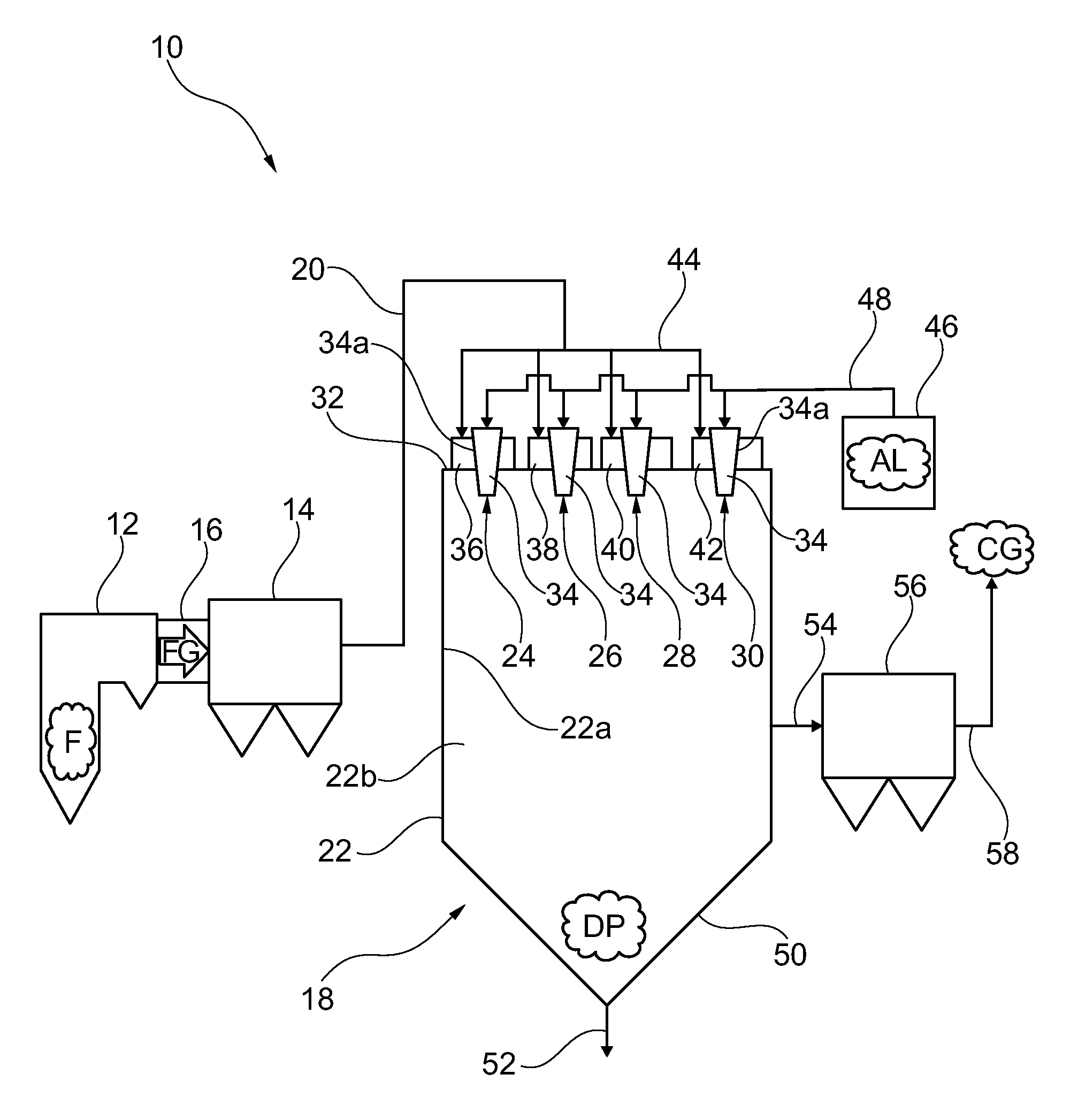
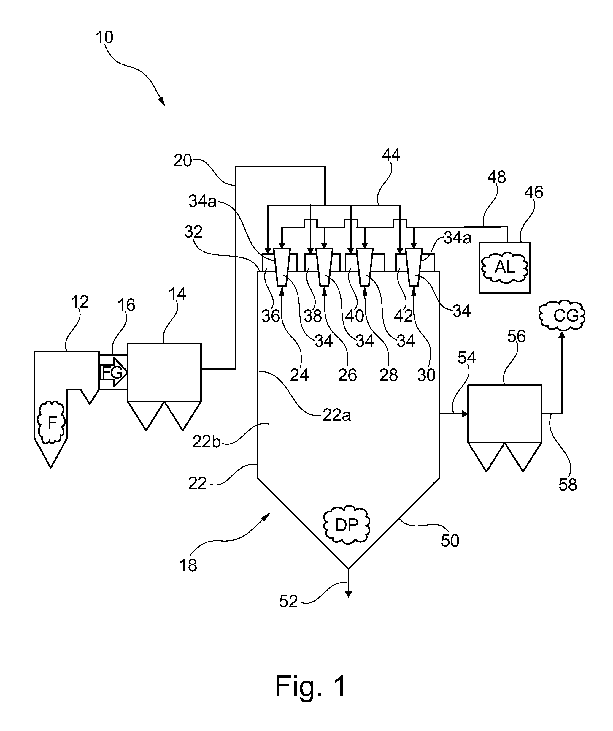
[0023]FIG. 1 is a schematic side view illustrating a power plant or waste-to-energy plant 10. Plant 10 comprises a boiler 12 in which a fuel F, such as coal, oil, or waste is combusted. Combustion of fuel F in boiler 12 generates a hot process gas in the form of a flue gas FG. Upon combustion, sulphur species contained in the fuel F form sulphur dioxide as a part of the flue gas FG. The combustion generated flue gas FG flows from the boiler 12 to a fluidly connected electrostatic precipitator 14 via fluidly connected duct 16. The electrostatic precipitator 14, an example of which is described in U.S. Pat. No. 4,502,872, is operable to remove dust particles from the flue gas FG. The flue gas FG, from which most of the dust particles have been removed, then flows to a fluidly connected spray dryer absorber (SDA)18 via fluidly connected duct 20. SDA 18 comprises a spray dryer chamber 22 and four dispersers 24, 26, 28, 30 mounted at a roof 32 of the spray dryer chamber 22. Four disperse...


PUM

PropertyMeasurementUnit
edge angleaaaaaaaaaa

Abstract

A spray dryer absorber operative for removing gaseous pollutants from a hot process flue gas and a vibrator device for removing accumulated deposits therefrom is provided. The spray dryer absorber includes a spray dryer chamber equipped with a plurality of dispersers and atomizers mounted at a roof of the spray dryer chamber. The vibrator device is operative to remove accumulated deposits from the spray dryer absorber and its components, such as its dispersers and atomizers, to avoid spray dryer absorber performance interference caused by such deposit accumulations.

Description

FIELD OF THE DISCLOSURE[0001]The present disclosure relates to a spray dryer absorber operative for removing gaseous pollutants from a hot process flue gas and a vibrator device for removing accumulated deposits therefrom. More specifically, the subject spray dryer absorber comprises a spray dryer chamber equipped with a plurality of dispersers mounted at a roof of the spray dryer chamber, each such disperser operative for dispersing a portion of the hot process flue gas around a respective atomizer operative for atomizing an absorption liquid, each disperser provided with a flow directing device operative for providing the respective portion of the hot process flue gas with a rotary movement around the atomizer as viewed from a top view of the spray dryer chamber, and a vibrator device operative to remove accumulated deposits from the spray dryer absorber and its components, such as its dispersers and atomizers, to avoid spray dryer absorber performance interference caused by depos...

Claims


Application Information

Patent Timeline
Patent Type & Authority Patents(United States)
IPC IPC(8): B08B7/04B01D53/50B05B15/02B08B7/00B01D53/18B08B7/02B08B5/00
CPCB05B15/0208B01D53/505B01D53/18B01D2251/404B01D2258/0283B08B5/00B08B7/00B08B7/02F23J2215/20F23J2219/50B01D53/1412
Inventor ZWAYYED, SALEEM, K.
Owner GENERAL ELECTRIC TECH GMBH
Features
  • Generate Ideas
  • Intellectual Property
  • Life Sciences
  • Materials
  • Tech Scout
  • Unparalleled Data Quality
  • Higher Quality Content
  • 60% Fewer Hallucinations
Learn More