Method and apparatus for high-power raman beam-combining in a multimode optical fiber

a multi-mode optical fiber and beam combination technology, applied in the field of fiber lasers and amplifiers, can solve the problems of power scalability, output power, lack of high efficiency, etc., and achieve the effects of eliminating higher-order stokes generation, high pump power, and high core-to-cladding area ratio

Active Publication Date: 2016-03-22
RAYTHEON CO
View PDF14 Cites 2 Cited by
  • Summary
  • Abstract
  • Description
  • Claims
  • Application Information

AI Technical Summary

Benefits of technology

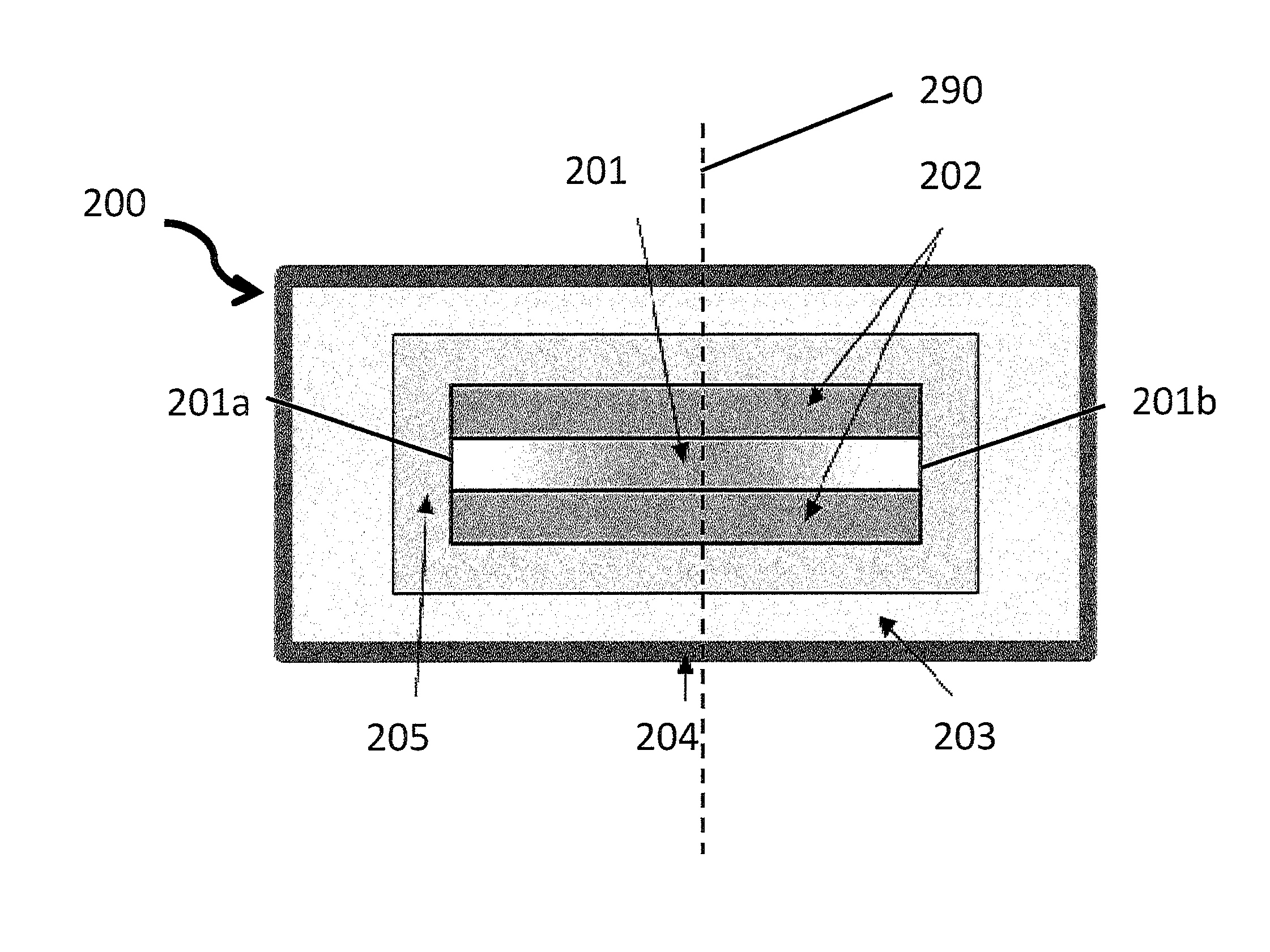
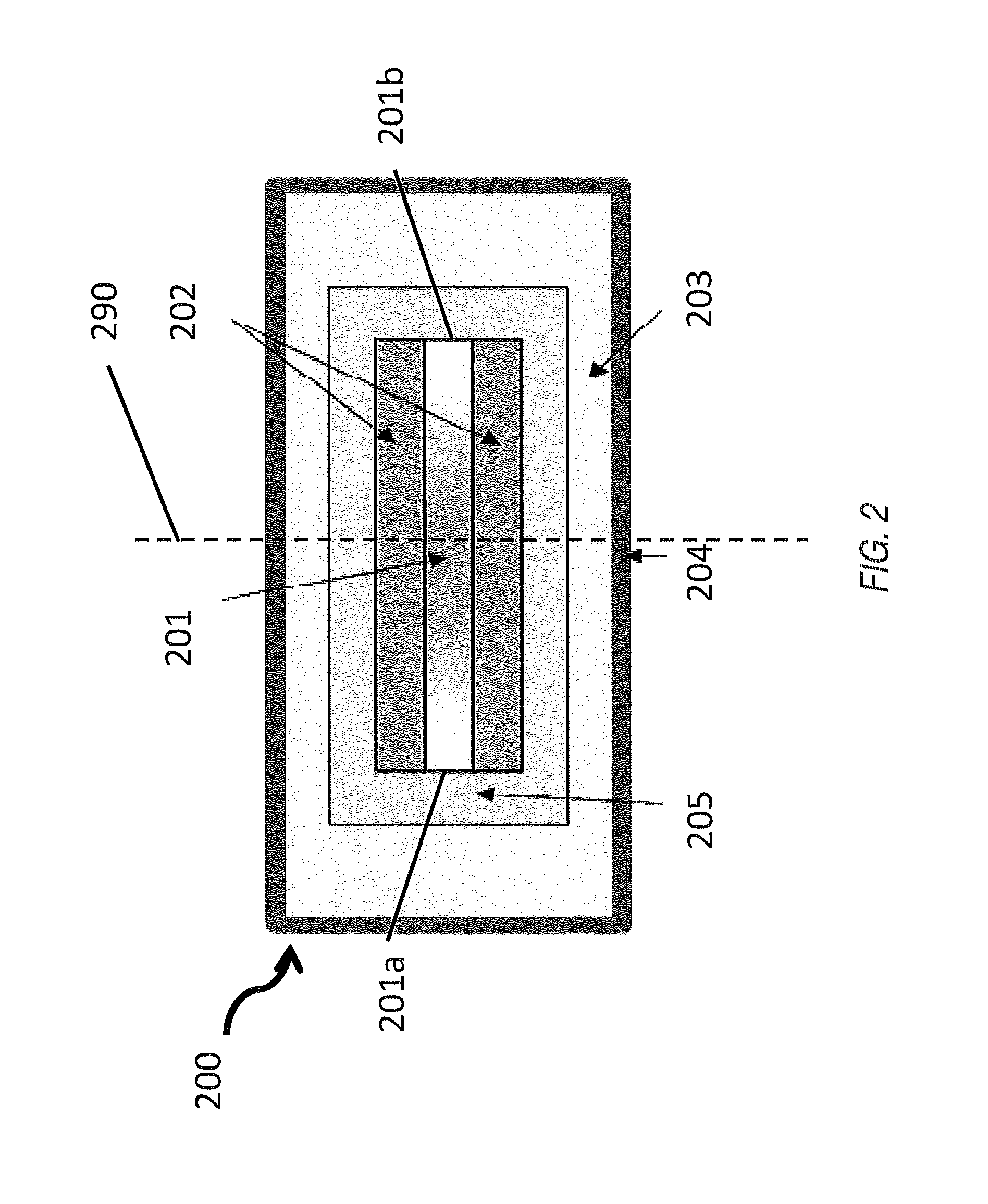
[0005]Certain embodiments may provide various technical advantages depending on the implementation. For example, a technical advantage of some embodiments having rectangular-shaped multi-mode core and pump cladding accommodating high pump power may include the capability to keep the ratio of core area to cladding area to a minimum of 0.25. Yet another technical advantage of some embodiments may include limiting the Raman log-gain product gIL to values about 10 that allows, in a combination with a high core-to-cladding area ratio, the elimination of higher-order Stokes generation. In such scenarios, the refractive indices satisfy the general relationship ns>nr>nc where ns is the index of refraction of the core, nr is the refractive index of the pump cladding and nc is the refractive index of the outer clad, to confine first Stokes signal within the fiber core and the pump light within the pump cladding. Yet another technical advantage of some embodiments may include the capability to maintain a monolithic, all-glass architecture. Still yet another technical advantage of some embodiments may include the capability to operate with broad spectral bandwidths per individual fiber channel such that stimulated Brillouin scattering (SBS) is no longer a limiting process, thereby allowing one to construct a high-power Raman laser using the most powerful available fiber lasers with spectral widths as broad as a few nm. Still yet another technical advantage of some embodiments may include the capability to increase lengths of individual fibers, since SBS is suppressed, thereby mitigating any thermal-loading challenges in the individual fiber amplifiers. Still yet another technical advantage of some embodiments may include the capability to obtain high beam-combining efficiencies of greater than 90%. Still yet another technical advantage may include the capability to produce robust good quality beams using gain-filtering and loss-filtering effects to suppress higher-order transverse modes of the core. The strength of the fundamental-mode selection can be enhanced, in some embodiments, by adding gradual refractive-index variations in the layers of the pump cladding adjacent to the large faces of the rectangular core, and by arranging for a lower index near the core axis with the index increasing near the narrow rectangular-core edges. As a result of this refractive-index variation, the numerical aperture (NA) of the core in the thin direction spatially varies along the wide core dimension. Still yet another technical advantage of some embodiments may include the capability to directly pump with high-brightness diode lasers, thereby eliminating the intermediate step, and efficiency reduction, of using the diode lasers to pump the individual fiber lasers that, in turn, pump the Raman laser. This is achieved by specifying that the rectangular shape of the pump cladding must have an etendue that is equal to or larger than the etendue of the pump-diode bars that are also assumed to have a rectangular geometry.

Problems solved by technology

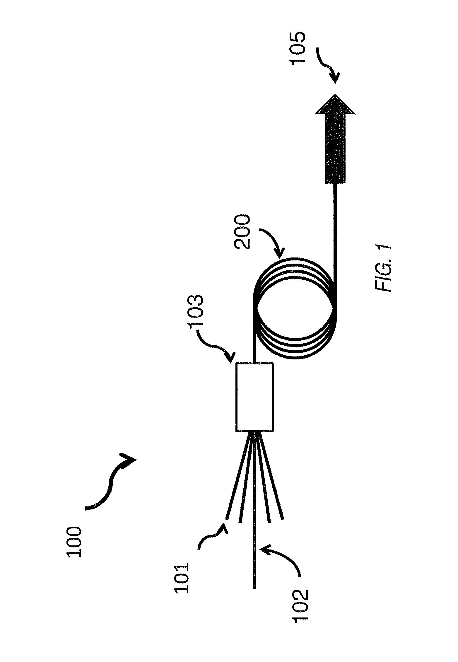
One of the difficult tasks in this field of fiber lasers is power scalability, since output power for individual fiber lasers and amplifiers is still limited to less than 10 kW due to the small lasing core area and heat-sink limitations.
Such techniques still suffer from one or more of the following: lack of high efficiency, degraded beam quality, constraints on individual laser characteristics, system complexity, packaging constraints and need for free-space optics or an optical bench.
These beam combining techniques still suffer from not being scalable to powers of 100 kW or more.

Method used


Image

  • Method and apparatus for high-power raman beam-combining in a multimode optical fiber
  • Method and apparatus for high-power raman beam-combining in a multimode optical fiber
  • Method and apparatus for high-power raman beam-combining in a multimode optical fiber

Examples


Embodiment Construction

[0013]It should be understood at the outset that, although example embodiments are illustrated below, the present invention may be implemented using any number of techniques, whether currently known or not. The present invention should in no way be limited to the example implementations, drawings, and techniques illustrated below. Additionally, the drawings are not necessarily drawn to scale.

[0014]Due to the limited power scalability of existing fiber lasers, beam combining techniques can be used to scale fiber-based laser sources to high powers. One of such beam combining technique is spectral beam combining (SBC). SBC involves overlapping multiple fiber lasers, each operating at a specific wavelength, at a common location on a diffraction grating. The angles of incidence of the individual beams systematically vary with the individual wavelengths such that all beams are diffracted by the grating into the same direction. Laser output powers of the order of tens of kW can be obtained...


PUM


Abstract

According to an embodiment of the disclosure, a system for producing a higher power laser beam is provided. The system includes an optical fiber having a length. The optical fiber is configured to receive inputs from multiple laser pumps and an input from a Stokes seed laser pump. The optical fiber has a core that is doped. The core, when viewed from a cross-section of the optical fiber, has a higher concentration of doping at a location near an axis of the optical fiber than a location further from the axis of the optical fiber. The optical fiber is also configured to convert pump power to Stokes power along the length of the optical fiber when subjected to a Stimulated Raman Scattering (SRS) process.

Description

TECHNICAL FIELD[0001]The present invention relates in general to fiber lasers and amplifiers and more particularly to a method and apparatus for high-power Raman beam-combining in a multimode optical fiber.BACKGROUND OF THE DISCLOSURE[0002]In the field of fiber lasers and amplifiers, recent developments have been focused on improving power, efficiency, beam quality and packaging characteristics. One of the difficult tasks in this field of fiber lasers is power scalability, since output power for individual fiber lasers and amplifiers is still limited to less than 10 kW due to the small lasing core area and heat-sink limitations. Nevertheless, there are a variety of applications that need a high-power laser source, and the primary approach to achieving this is to employ a beam combining (BC) technique to produce a multi-fiber laser source that can be scalable to high power. Such techniques still suffer from one or more of the following: lack of high efficiency, degraded beam quality,...

Claims


Application Information

Patent Timeline
Patent Type & Authority Patents(United States)
IPC IPC(8): H01S3/30G02B6/28H01S3/16H01S3/042H01S3/067H01S3/094
CPCH01S3/302H01S3/0672H01S3/06729H01S3/06754G02B6/2821H01S3/042H01S3/06704H01S3/06733H01S3/09408H01S3/094007H01S3/1695
Inventor ROCKWELL, DAVID A.SHKUNOV, VLADIMIR V.
Owner RAYTHEON CO
Why Eureka
Try Eureka