High-voltage, low-inductance gas switch

a gas switch, high-voltage technology, applied in the direction of electronic switching, electric discharge tubes, pulse techniques, etc., can solve problems such as problems in some applications, and achieve the effect of uniform electric field

Active Publication Date: 2016-03-22
NAT TECH & ENG SOLUTIONS OF SANDIA LLC
View PDF5 Cites 11 Cited by
  • Summary
  • Abstract
  • Description
  • Claims
  • Application Information

AI Technical Summary

Benefits of technology

[0008]The present invention is directed to a high-voltage, low-inductance gas switch, comprising a hollow housing pressurized with a gas; a pair of axially symmetric opposing high voltage electrodes spaced apart and located on a centerline within the pressurized housing; and an annular trigger ring disposed on a midplane between the opposing high voltage electrodes, wherein the surfaces of the trigger ring and the opposing high voltage electrodes are shaped to provide a uniform electric field in the gap formed therebetween. The surfaces of the high voltage electrodes can have a modified Rogowski profile and the annular trigger ring can have a double concave (de-enhanced) inner surface to provide the uniform electric field. For example, the pressurized gas can comprise dry air, nitrogen, hydrogen, or sulfur hexafluoride. The housing is preferably cylindrically symmetric about the centerline with internal threads on each end and each high voltage electrode can be mounted on an externally threaded insulating end piece that can be rotatably inserted into opposing ends of the housing, thereby enabling adjustment of the spacing of the electrodes therebetween. The annular trigger ring can be mounted on the inside wall of an insulating tubular liner and the outside wall of the tubular liner can be compressibly sealed to the inner wall of the housing when the housing is pressurized. At least one spark plug can be provided at the midplane to provide a spark to pre-ionize the pressurized gas.

Problems solved by technology

However, it operated at relatively high pressure (e.g., 242 psia) which can pose problems in some applications.

Method used


Image

  • High-voltage, low-inductance gas switch
  • High-voltage, low-inductance gas switch
  • High-voltage, low-inductance gas switch

Examples


Embodiment Construction

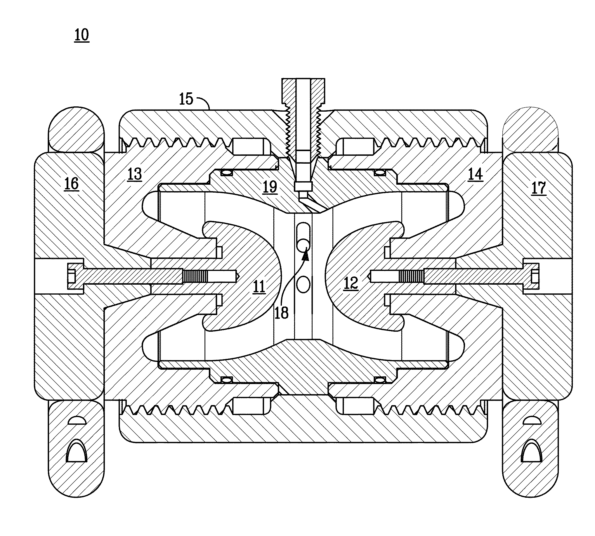
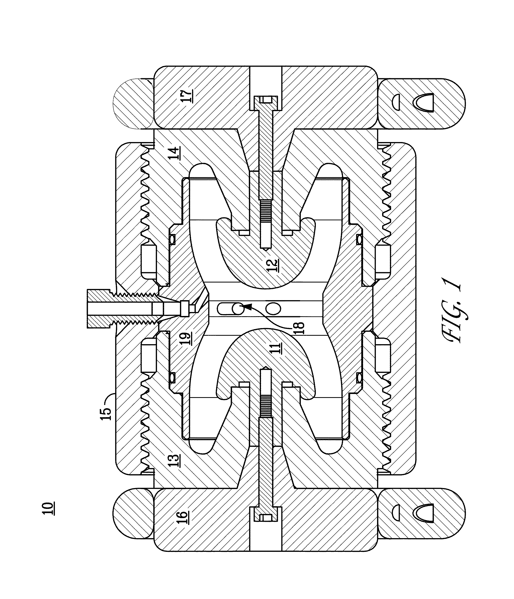
[0026]FIG. 3A is a cross-sectional side view illustration of an exemplary high-voltage, low-inductance gas switch 20 of the present invention. FIG. 3B is a cutaway perspective view illustration of the gas switch 20. FIG. 3C is an exploded view illustration of the gas switch 20 which shows the dissembled switch. The gas switch 20 is preferably axially symmetric about a centerline. The switch 20 comprises an insulating hollow housing 25 that can be internally threaded to contain a high pressure gas. For example, the housing 25 can comprise a reinforced plastic (e.g., glass-reinforced polyetherimide or Nylon 66) or other suitable high-strength insulating material. Importantly, the switch 20 comprises a midplane annular trigger ring 28 having a double concave inner profile that wraps completely around the ends of opposing high-voltage electrodes 21 and 22. The inner profile of the trigger ring 28 and the ends of opposing high voltage electrodes 21 and 22 can be shaped to provide a unifo...


PUM


Abstract

A low-inductance, air-insulated gas switch uses a de-enhanced annular trigger ring disposed between two opposing high voltage electrodes. The switch is DC chargeable to 200 kilovolts or more, triggerable, has low jitter (5 ns or less), has pre-fire and no-fire rates of no more than one in 10,000 shots, and has a lifetime of greater than 100,000 shots. Importantly, the switch also has a low inductance (less than 60 nH) and the ability to conduct currents with less than 100 ns rise times. The switch can be used with linear transformer drives or other pulsed-power systems.

Description

CROSS-REFERENCE TO RELATED APPLICATION[0001]This application claims the benefit of U.S. Provisional Application No. 61 / 752,259, filed Jan. 14, 2013, which is incorporated herein by reference.STATEMENT OF GOVERNMENT INTEREST[0002]This invention was made with Government support under contract no. DE-AC04-94AL85000 awarded by the U. S. Department of Energy to Sandia Corporation. The Government has certain rights in the invention.FIELD OF THE INVENTION[0003]The present invention relates to pulsed-power technology and, in particular, to a high-voltage, low-inductance gas switch that can be used in linear-transformer-driver cavities.BACKGROUND OF THE INVENTION[0004]Linear transformer drivers (LTDs) are a relatively new technology being developed because of their potential to provide high performance and greater versatility of applications at a significantly reduced cost. LTDs can potentially achieve compactness and low cost by going directly from DC-charged capacitors to a 100-ns pulse pr...

Claims


Application Information

Patent Timeline
Patent Type & Authority Patents(United States)
IPC IPC(8): H01J7/24H03K17/52
CPCH03K17/52
Inventor GRUNER, FREDERICK R.STYGAR, WILLIAM A.
Owner NAT TECH & ENG SOLUTIONS OF SANDIA LLC
Why Eureka
Try Eureka