Apparatus and methods for hypersonic nosecone

a technology of nosecone and apparatus, which is applied in the field of systems, apparatus and methods for the reduction of drag in spacecraft or missiles, can solve the problems of nosecone increasing beyond the failure point, and achieve the effect of reducing drag

Active Publication Date: 2016-03-29
JANEKE CHARL E
View PDF18 Cites 1 Cited by
  • Summary
  • Abstract
  • Description
  • Claims
  • Application Information

AI Technical Summary

Benefits of technology

[0005]Illustrated herein is a method for reducing drag at hypersonic speed that includes the steps of mounting a liquefacting nosecone on the forward portion of a projectile; where the projectile is either a missile or spacecraft.
[0006]Further describes is a method for reducing drag at hypersonic speed also having the steps of drawing an atmosphere external to the liquefacting nose cone an intake aperture or a discharge shaft.

Problems solved by technology

The reduction of drag in spacecraft and missiles is of particular concern as atmospheric friction can cause the nosecone to increase beyond the failure point.

Method used


Image

  • Apparatus and methods for hypersonic nosecone
  • Apparatus and methods for hypersonic nosecone
  • Apparatus and methods for hypersonic nosecone

Examples


Embodiment Construction

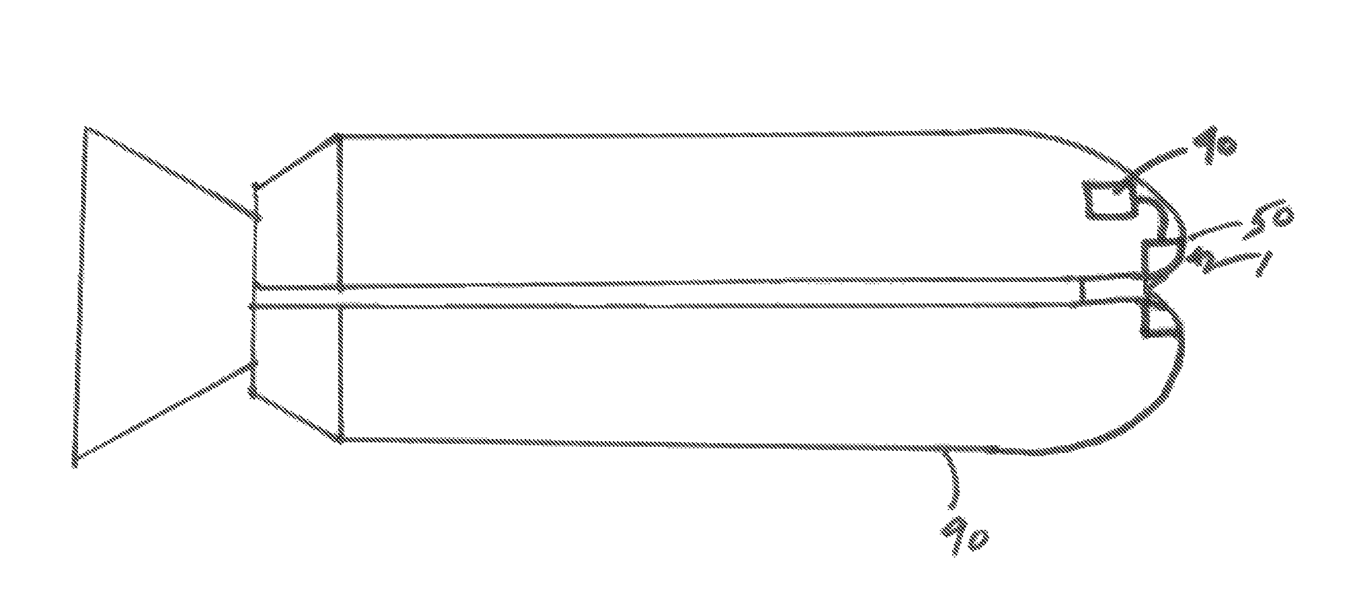
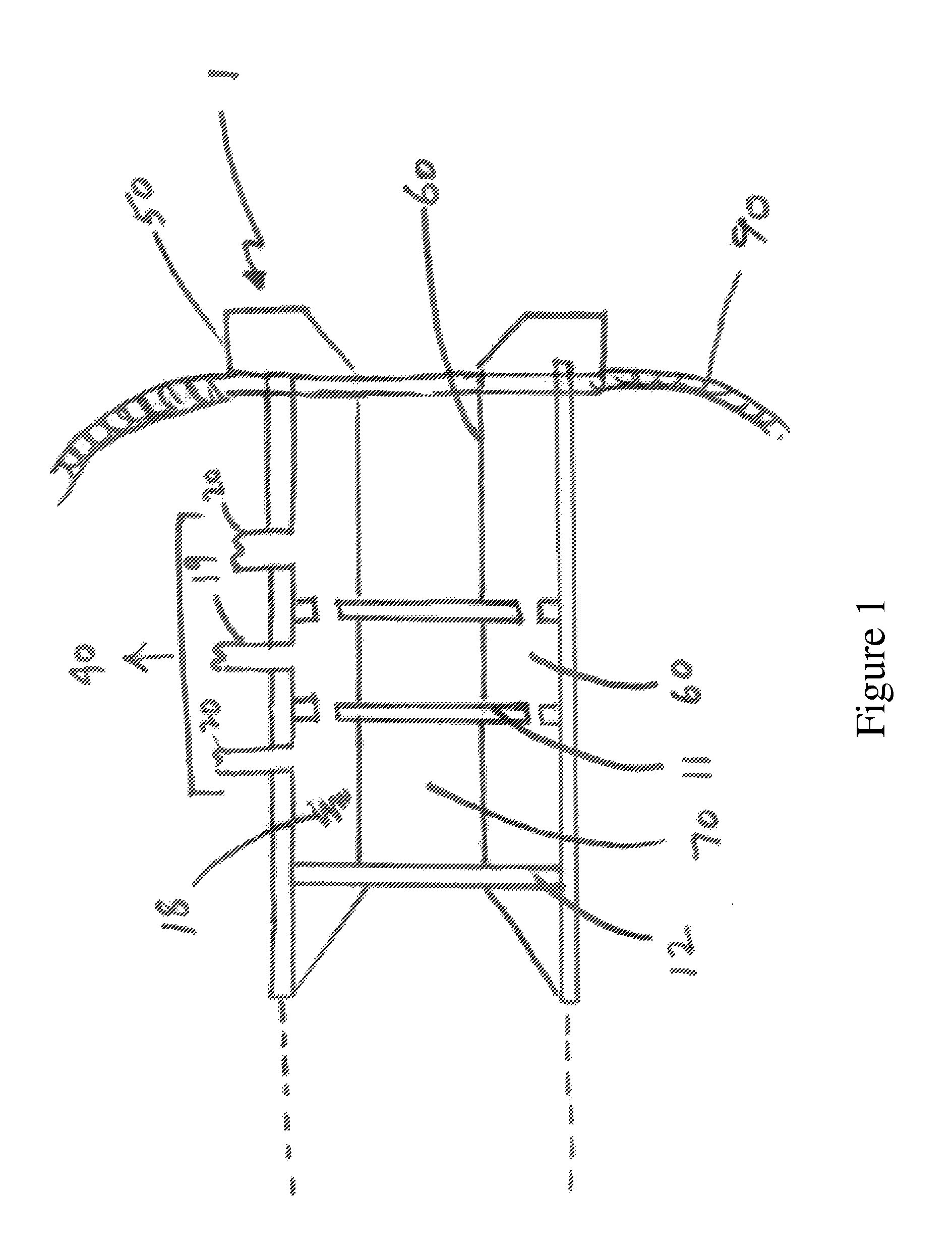
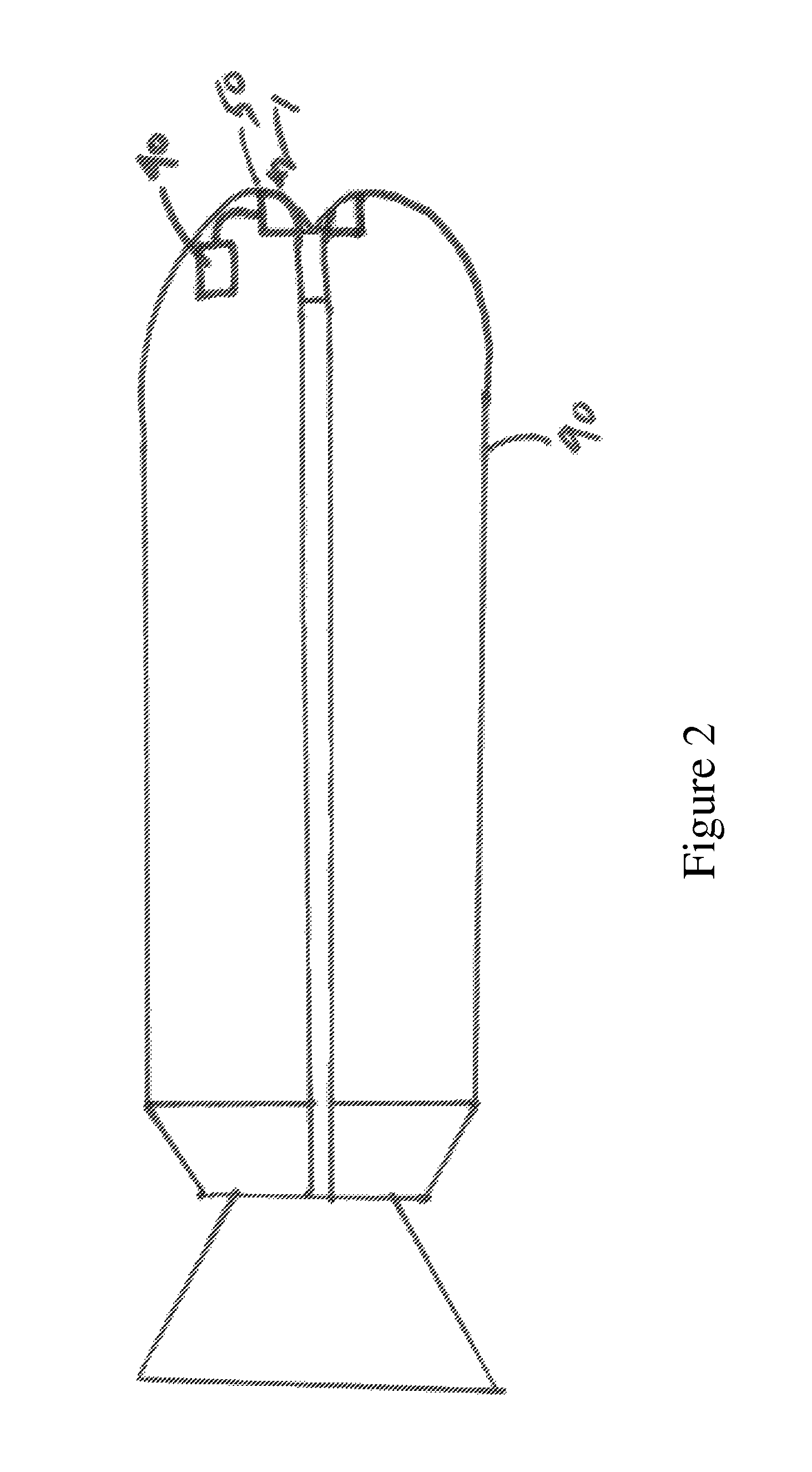
[0014]Referring to FIG. 1 which illustrates the components of the conductive nose cone 1. A cooling fluid 18, typically liquid nitrogen, circulates by injection by the input line 19 into the shaft 60, and exiting via the exit lines 20. The cooling fluid 18 is provided by the cooling fluid source 40.

[0015]Inside the shaft 60, is a space for the cooling fluid 18. A perforated Teflon w washer 11, glass tube 12, laser aiming point 13 and thermocouple sensor probe 14. The incoming hypersonic streamline 17 is instantaneously transformed into a rotation vector as a consequence of rapid harmonic / isothermal compression surges on the reaction plane 112.

[0016]The thermally conductive cone 1 is composed of a tip 50, a shaft 60, and a bore 70. The entry part of the tip 50 has an intake area that is larger in circumference that the bore 70. The angle of intake area is approximately 30-60 degrees relative to a line drawn in parallel with the bore edge. In a representative embodiment, the intake bo...


PUM


Abstract

An apparatus and method for mitigating the shock front or reducing drag of a rocket or aerospace plane flying at hypersonic speeds by using a modified nose cone that incorporates a low temperature substance, such as liquid nitrogen, and where the nose cone simultaneously interacts with the ambient air to further supercool the nose cone during operation.

Description

CROSS REFERENCE TO RELATED APPLICATIONS[0001]The present application claims the benefit of U.S. Utility patent application Ser. No. 14 / 313,976, filed on Jun. 24, 2014 and entitled “Thermally Conductive Hypersonic Nosecones” and U.S. Provisional Patent Application No. 61 / 838,454, filed on Jun. 24, 2013 and entitled “Hypersonic Vortex Tube,” which is herein incorporated by reference in its entirety.GOVERNMENT FUNDING[0002]No government funding was utilized for this invention.BACKGROUND[0003]This inventive subject matter relates to the systems, apparatus, and methods for the reduction of drag in a spacecraft or missiles. The reduction of drag in spacecraft and missiles is of particular concern as atmospheric friction can cause the nosecone to increase beyond the failure point. Clearly ways to reduce would benefit missiles, allowing them to travel at higher speeds, and spacecraft, allowing them to reenter the atmosphere without the fear of destruction.SUMMARY OF THE INVENTION[0004]The i...

Claims


Application Information

Patent Timeline
Patent Type & Authority Patents(United States)
IPC IPC(8): B64C1/38F42B12/02F42B15/34B64G1/62
CPCF42B12/02B64G1/62F42B15/34F42B10/46B64G1/58
Inventor JANEKE, CHARL, E.
Owner JANEKE CHARL E
Why Eureka
Try Eureka