Laser illumination scanning

a laser illumination and scanning technology, applied in optics, instruments, static indicating devices, etc., can solve the problems of slow refresh rate, large optical system size, and inability to project illumination of led array scanning systems for display technologies with large optical systems,

Active Publication Date: 2016-03-29
MICROSOFT TECH LICENSING LLC
View PDF429 Cites 24 Cited by
  • Summary
  • Abstract
  • Description
  • Claims
  • Application Information

AI Technical Summary

Benefits of technology

[0004]This Summary introduces simplified concepts of laser illumination scanning, and the concepts are further described below in the Detailed Description and/or shown in the...

Problems solved by technology

As an emerging technology, there are many challenges and design constraints with augmented reality, from generation of the virtual objects and images so that they appear realistic in a real environment, to developing the optics small and precise enough for implementation with a wearable display device.
There are also challenges to developing illumination sources for implementation as micro projectors and/or imaging units for wearable display devices.
Although OLED cells can be individually controlled for illumination, unlike the LCOS material, the OLEDs are not viable for projection illumination because they do not emit enough light....

Method used


Image

  • Laser illumination scanning
  • Laser illumination scanning
  • Laser illumination scanning

Examples


Embodiment Construction

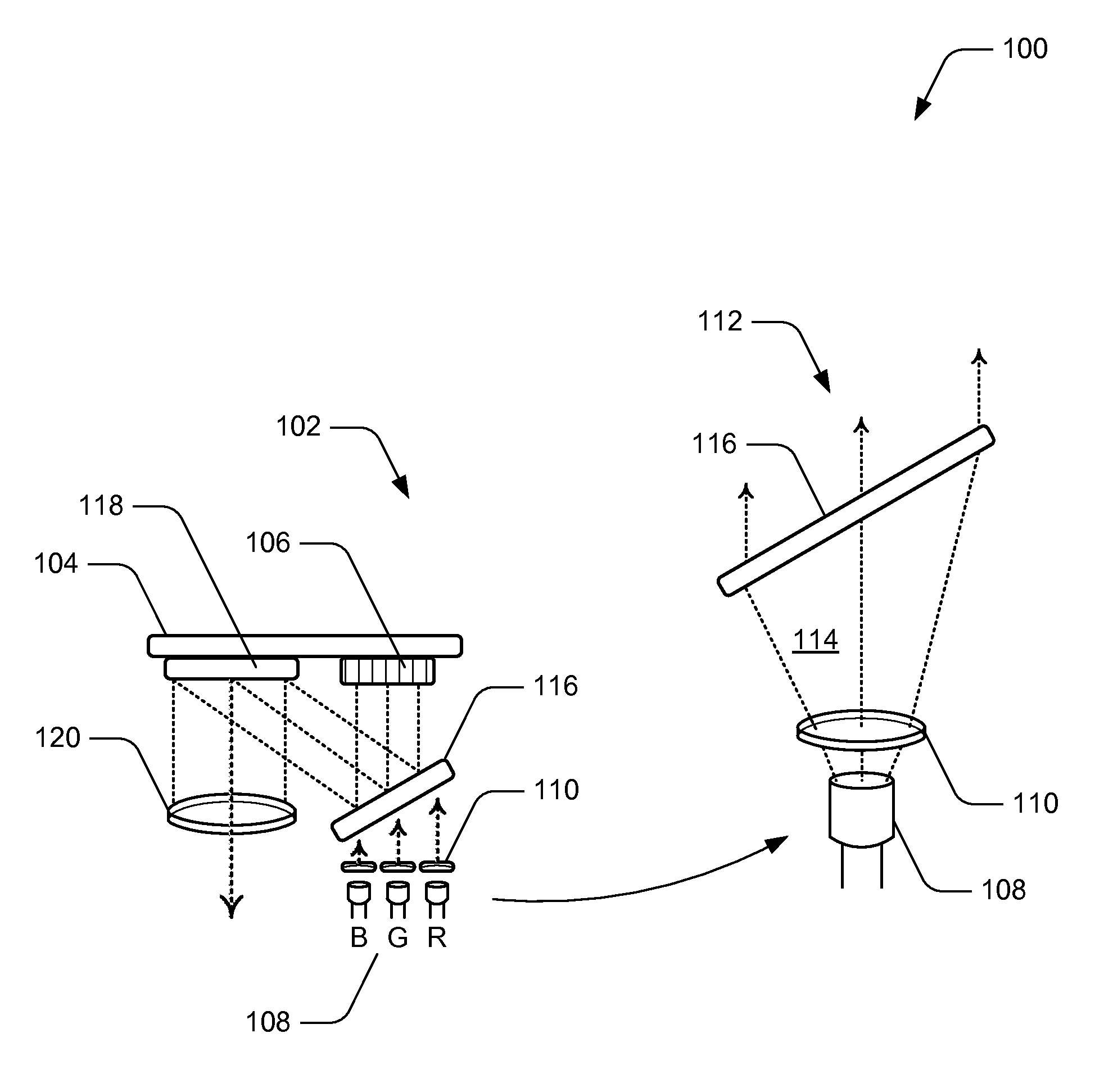
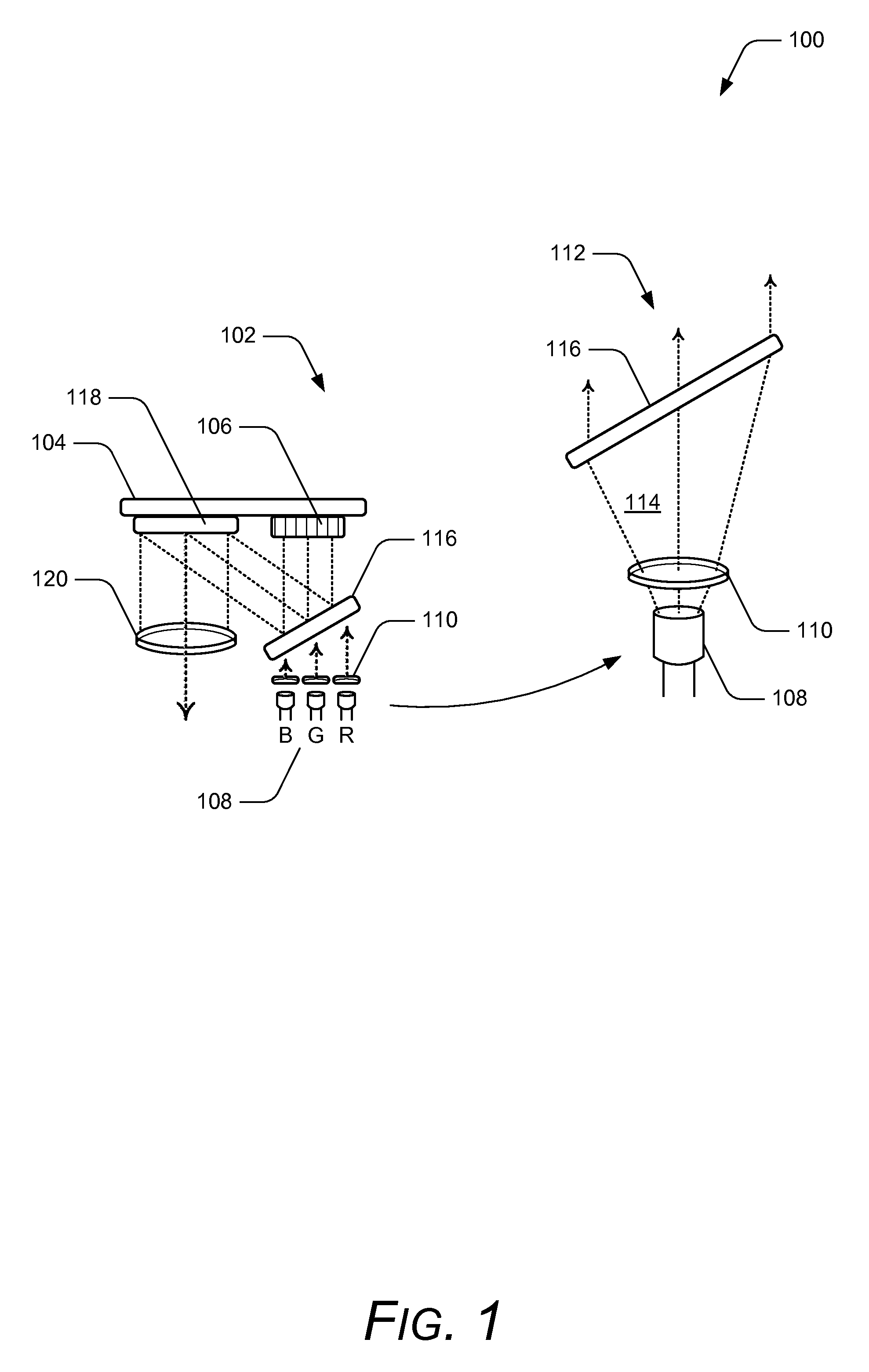
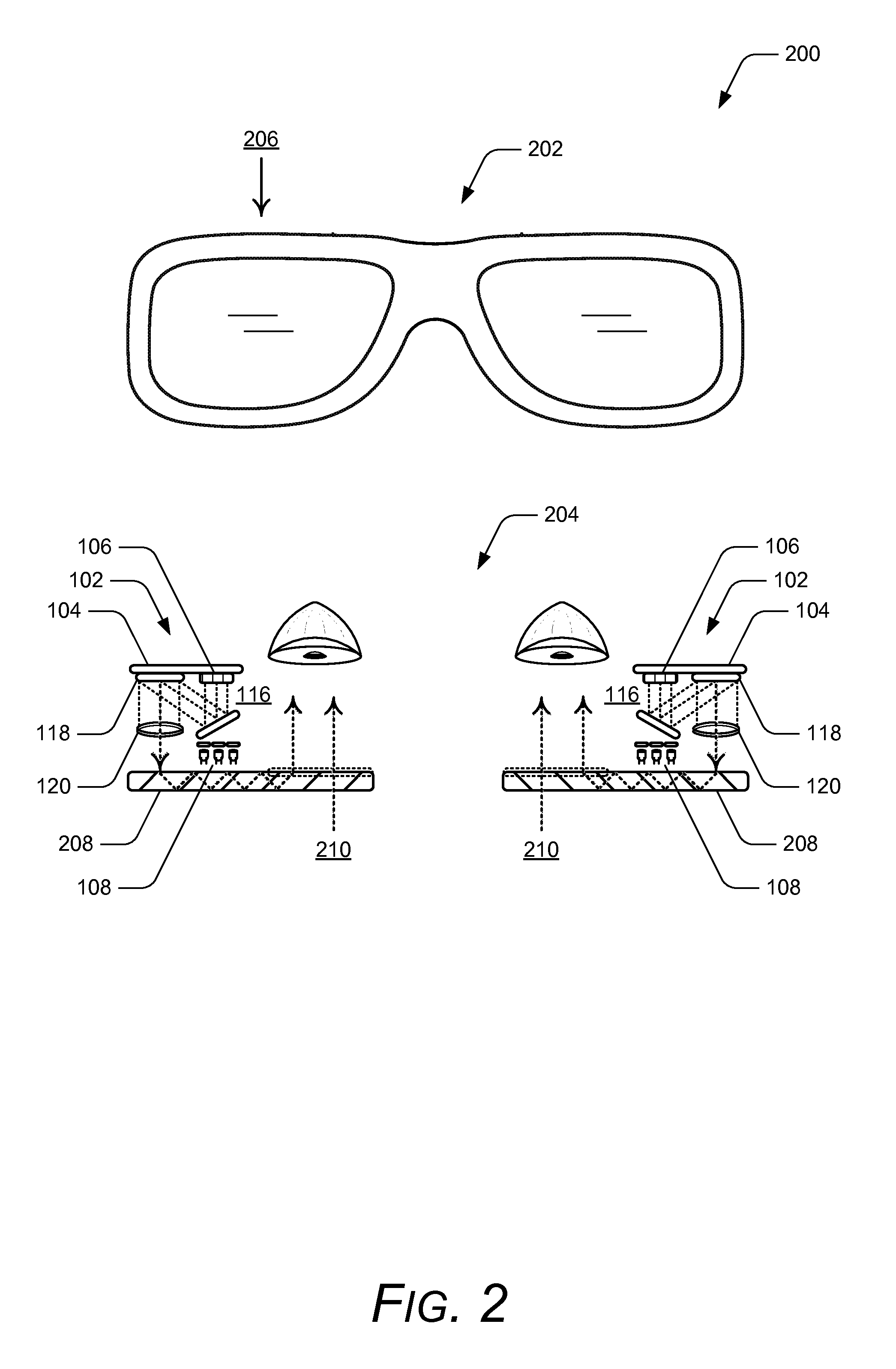
[0013]Embodiments of laser illumination scanning are described. An imaging system of a wearable display device (e.g., glasses or a head-mounted display) can include left and right imaging units that generate a virtual image for display and viewing. In a scanning system, lasers can be implemented to illuminate a linear array of spatial light modulators that are scanned to generate a two-dimensional image for display or projection. For example, red, green, and blue (RGB) lasers emit RGB light that illuminates the linear array of spatial light modulators, which is then reflected through optics onto a scanning mirror and directed into a waveguide or otherwise projected. The lasers and linear array of spatial light modulators provides a reduction in size over a conventional linear array, as well as a corresponding reduction in the size of the optics that can be implemented for a wearable display device.

[0014]While features and concepts of laser illumination scanning can be implemented in...


PUM


Abstract

In embodiments of laser illumination scanning, an imaging unit includes a linear array of spatial light modulators that direct light in a direction perpendicular to an imaging scan direction. The lasers each emit the light through a diffractive optic that uniformly illuminates the spatial light modulators, and a scanning mirror then scans the spatial light modulators to generate a two-dimensional image for display. The lasers can include red, green, and blue lasers for RGB illumination of the spatial light modulators, which can be implemented as reflective liquid crystal on silicon (LCOS), transmissive LCOS, or as micro-electro-mechanical systems (MEMS) mirrors.

Description

BACKGROUND[0001]Virtual reality can be viewed as a computer-generated simulated environment in which a user has an apparent physical presence. A virtual reality experience can be generated in 3D and viewed with a head-mounted display (HMD), such as glasses or other wearable display device that has near-eye display panels as lenses to display a virtual reality environment, which replaces the actual environment. Augmented reality, however, provides that a user can still see through the display lenses of the glasses or other wearable display device to view the surrounding environment, yet also see images of virtual objects that are generated for display and appear as a part of the environment. Augmented reality can include any type of input such as audio and haptic inputs, as well as virtual images, graphics, and video that enhances or augments the environment that a user experiences. As an emerging technology, there are many challenges and design constraints with augmented reality, fr...

Claims


Application Information

Patent Timeline
IPC IPC(8): G02B27/14G09G5/00G02B26/00G02B27/01
CPCG02B27/017G02B26/00G02B2027/0178
Inventor BOHN, DAVID, D.FLECK, ROD, G.
Owner MICROSOFT TECH LICENSING LLC
Why Eureka
Try Eureka