Method and apparatus for integrated electric power generation, storage and supply distributed and networked at the same time

a technology of integrated electric power generation and storage, applied in the direction of battery/fuel cell control arrangement, emergency power supply arrangement, greenhouse gas reduction, etc., can solve the problems of affecting the performance and safety of vehicles, the loss of 20% of the battery performance level, and the general degradation of electric car batteries. , to achieve the effect of cost saving, less vulnerable and cost effectiv

Active Publication Date: 2016-03-29
ENERGY STORAGE & RETENTION SOLUTIONS HLDG LLC
View PDF14 Cites 0 Cited by
  • Summary
  • Abstract
  • Description
  • Claims
  • Application Information

AI Technical Summary

Benefits of technology

[0011]Additionally, using car batteries for energy storage in residential / commercial applications makes use of the higher energy densities of such batteries, as the auto industry continues to improve the stored energy per kg of weight factor to improve the distance a vehicle travels per single battery charge. This higher energy density makes for more compact residential storage units. The car industry is anticipating improvements in capacity of electric car batteries at about 8-10% each year. See, e.g., http: / / www.hybridcars.com / news / 13-key-questions-and-answers-about-nissan-leaf-battery-pack-and-ordering-28007.html for a description of battery improvements in the context of hybrid cars. If the anticipated improvements are realized, this will further reduce battery weight and increase energy storage capacity. Thus energy storage capacity for the same size and weight can be expected to double in about 8 years. Accordingly, in another embodiment, the disclosure provides a distributed power storage and generation system with high performance and low energy storage cost by making use of these advancements of the electric car battery industry in utilizing the huge number of these car batteries which are available for recycling.
[0013]The various embodiments of the disclosed cost effective and less vulnerable integrated power systems are characterized in that each is created with no single point of failure. They are thus not only cost effective, but also are not vulnerable to a power failure or blackout of grid power. The system is replenishing, re-charging and storing energy from the grid during low-load (night) times, when grid electricity is less expensive and when renewable sources (e.g., hydro-electrical) are oftentimes able to generate a significant amount of the power requirement. (The words “energy” and “power” are used interchangeably herein). Also, the cell uses all other renewable energy (photovoltaic, wind, geo-thermal, etc.) generated on-site and stores that renewable energy for later use. “On-site” as used in this context means in the vicinity of the site of the cell or at a reasonable distance therefrom for transporting electrical energy from the renewable energy source to the cell site. This eliminates the need to send this surplus energy to utilities which requires additional systems and fees. The cell system is more self-sustained and independent, and can meet all energy needs of its end users including back-up power for emergencies. The “cell” referred to herein is an electric power retention distribution cell. For simplicity in the disclosure it is referred to simply as a “cell” with it understood that it is an electric power retention distribution cell that also functions to connect the components of the cell and connect the end users to one or more electrical networks.

Problems solved by technology

Electrical car batteries generally degrade during the years of service and become less efficient for meeting demanding requirements of the automobile industry, for instance, rapid acceleration with quick discharging and charging needs.
For example, loss of 20% of the battery performance level may have significant impact on a vehicle's performance and safety.

Method used


Image

  • Method and apparatus for integrated electric power generation, storage and supply distributed and networked at the same time
  • Method and apparatus for integrated electric power generation, storage and supply distributed and networked at the same time
  • Method and apparatus for integrated electric power generation, storage and supply distributed and networked at the same time

Examples


Embodiment Construction

[0039]Embodiments of the present disclosure will be described in detail with reference to the drawings. In the drawings, parts that are the same or correspond to each other have been given the same reference signs, and redundant descriptions thereof will not be given.

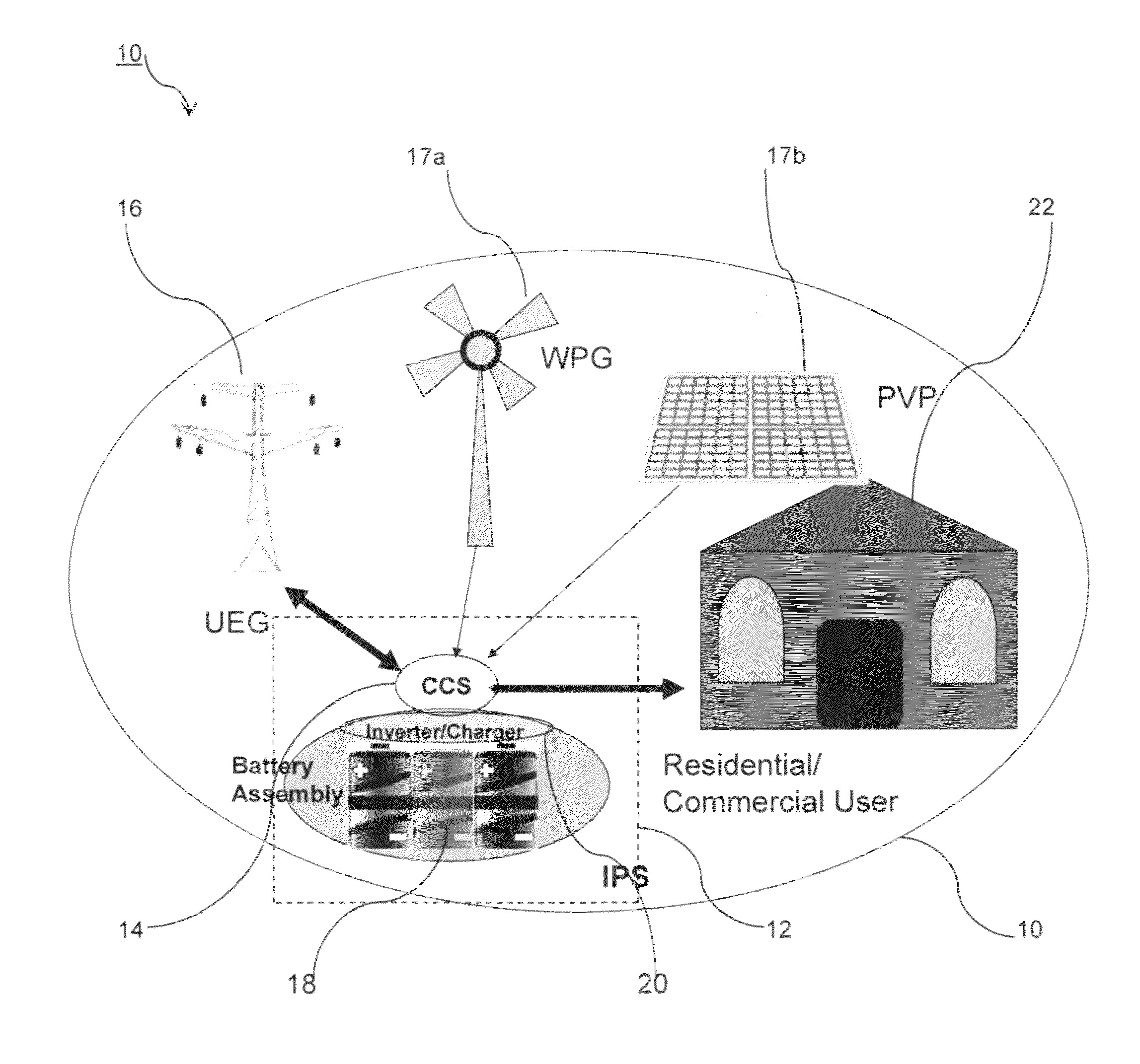
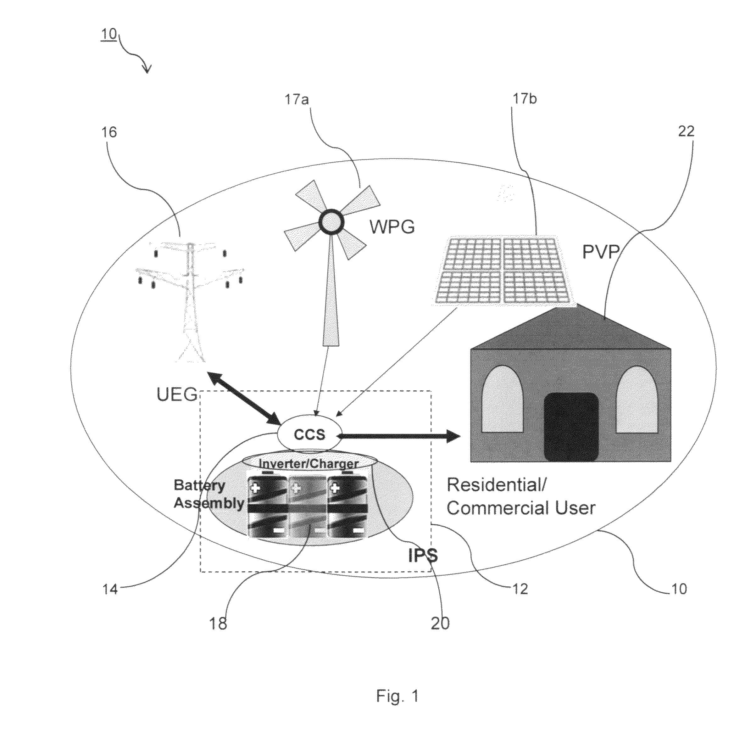
[0040]Electric car batteries at the end of their automotive life can still have about 70 to 80% of their charging capacity when new. Unlike a battery's use in vehicles where conditions are fairly demanding with rapid discharging and charging, a residential / commercial use of the same battery gives the battery a “second life” once its automotive application is finished. Use of “recycled” batteries also favorably adds to the cost / benefit of the system of the disclosure. The stored energy will meet full energy needs for days and when it is not in use, and can be preserved, nominally for up to a month, while also being available to meet any emergency back-up power situation.

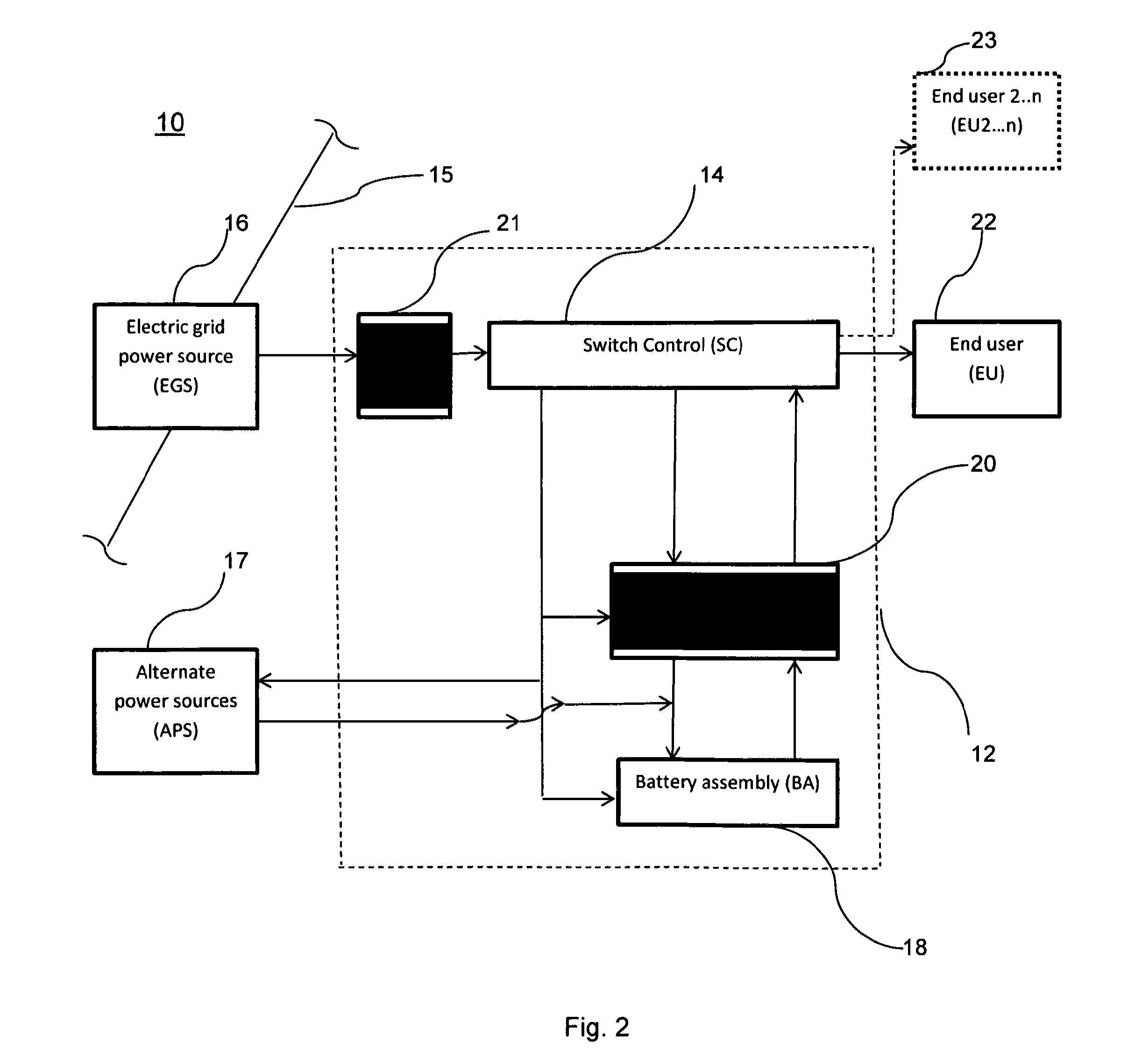
[0041]Referring now to FIGS. 1 and 2, FIG. 1 is a p...


PUM


Abstract

An electric power retention distribution cell supplies stored electrical power as the primary electric supply to an end user at predetermined times. The cell has a rechargeable battery assembly, a bi-directional inverter and a switch control, and is connected to an electric utility grid, to one or more end users and to alternate power generation sources, such as wind or solar. The battery assembly is charged from the alternate power generation source and from grid power, and the cell is switched at selected times to provide the primary electric supply from stored electric power in the cell to the end user. A circuit of the battery assembly gives an extended electric power storage time by controlling storage parameters. Networks using the electric cell are also described for a utility hub network formed using two or more cells, and for a regional utility hub network formed using multiple utility hubs.

Description

CROSS-REFERENCE TO RELATED APPLICATION[0001]This application claims the benefit of priority under 35 U.S.C. 119(e) to U.S. Provisional Application No. 61 / 459,586 filed on Dec. 16, 2010, the disclosure of which is incorporated herein by reference.BACKGROUND OF THE DISCLOSURE[0002]1. Technical Field[0003]The present disclosure relates to systems for electric power generation, storage and distribution.[0004]2. Description of Related Art[0005]Current electric power generation and distribution is centralized. As such, large scale power generation and distribution lacks flexibility, resilience and is vulnerable to large scale blackouts and catastrophic regional emergences. These issues are recognized globally. Currently many governments (US, Japan, EU, etc.) are sponsoring long-term efforts to resolve these type of issues. The “centralized approach” is also very inefficient and costly, and hence not feasible, when it comes to energy generation and storage due to lack of a mature and cost ...

Claims


Application Information

Patent Timeline
Patent Type & Authority Patents(United States)
IPC IPC(8): H02J1/00H02J3/38H02J9/00H02J3/32
CPCH02J3/382H02J3/383H02J3/386H02J3/32Y02E10/563Y02E10/566Y02E10/763Y02E70/30Y10T307/344Y10T307/696B60L50/52B60L53/20H02J2300/40H02J2300/28H02J2300/20H02J2300/24H02J3/381B60L53/62B60L58/15Y02E10/56Y02E10/76Y02T10/70Y02T10/92Y02T90/12Y02T10/7072Y02T90/14H02J3/46H02J7/00H02J2207/20B60L53/60H02M7/68
Inventor NAZARIAN, ASHOT
Owner ENERGY STORAGE & RETENTION SOLUTIONS HLDG LLC
Why Eureka
Try Eureka