
Brake test bench having an electrical brake actuator and method for same

a technology of brake actuator and test bench, which is applied in the direction of braking system, structural/machine measurement, instruments, etc., can solve the problems of requiring a large amount of construction complexity (special valves, friction-reduced and force-lubricated cylinders), and achieve the effect of reliable and safe manner

Active Publication Date: 2016-04-05
HORIBA EURO
View PDF19 Cites 3 Cited by
  • Summary
  • Abstract
  • Description
  • Claims
  • Application Information

AI Technical Summary

Benefits of technology

[0013]The invention provides a brake test bench having an electrical brake actuator and a method for improving the repeat accuracy of the simulated brake applications that overcome the hereinafore-mentioned disadvantages of the heretofore-known devices and methods of this general type and that provide such features with simulating a vehicle driver's foot with a brake actuator and with an appropriate braking force and a sufficient pressure build-up rate. Therein, it is not intended to modify the brake system in the vehicle comprising the brake but, rather, to maintain the brake hydraulic system that is usually present.
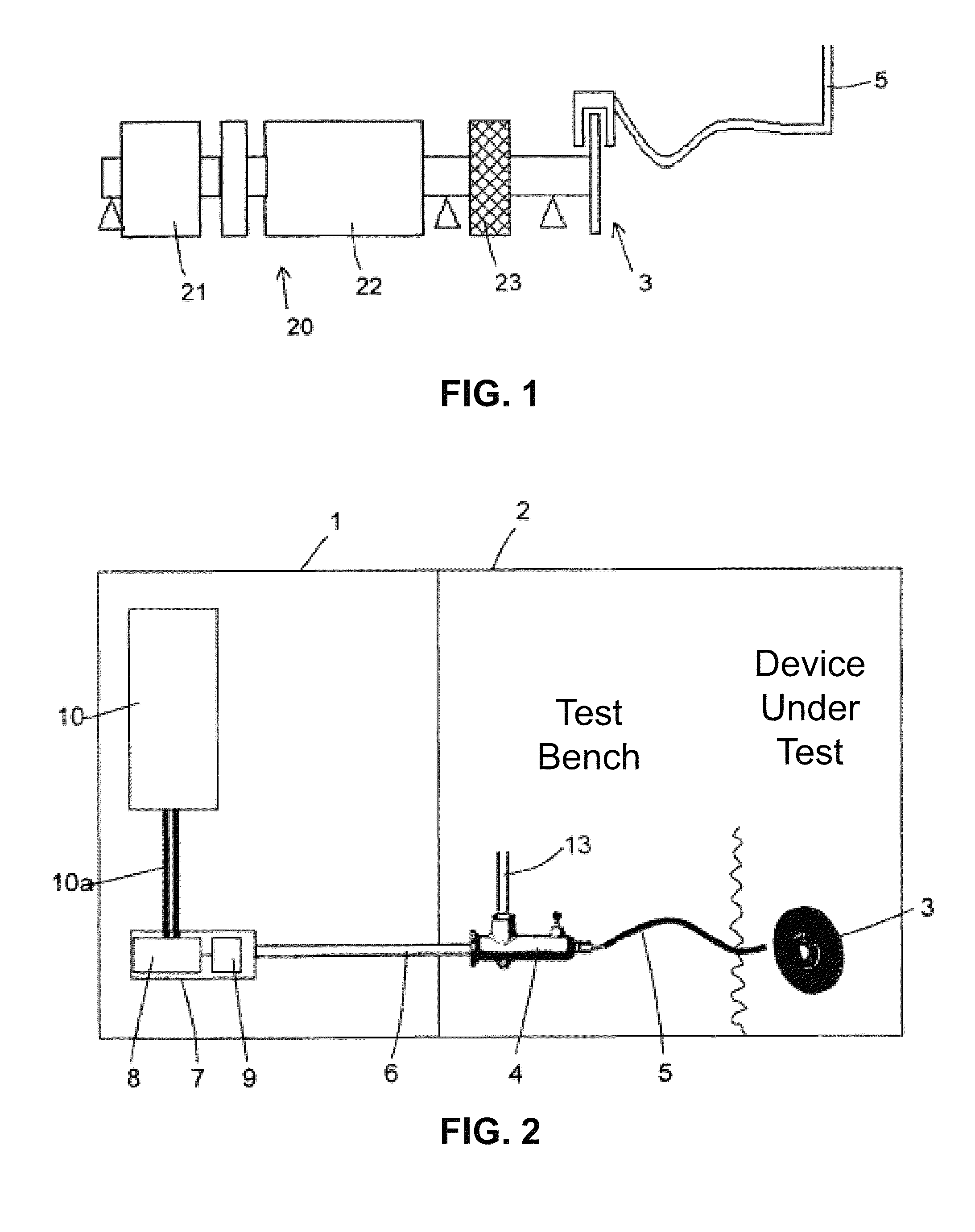
[0015]Therein, the brake itself is not an integral part of the test bench but forms the unit under test. Therefore, the brake actuator comprises the electric motor and the planetary roller screw drive driven by the electric motor. Such a planetary roller screw drive is, for example, known from European Patent Application EP 1 655 513 A1 corresponding to U.S. Patent Publication Nos. 2006 / 0196293 and 2006 / 0214453 to Gerhardt, and which is incorporated herein by reference. In a planetary roller screw drive, the electric motor drives a planetary gear set in a rotary movement, the planetary gear set rolling in an internal thread, thereby changing its position in axial direction. A brake actuator that is configured in such a manner allows for producing high forces within a very short time, which can then accordingly generate high brake pressures for the brake to be tested through the brake pressure generating assembly. The braking foot of a vehicle driver can be excellently simulated by such a configuration without having to put up with curtailments therein.
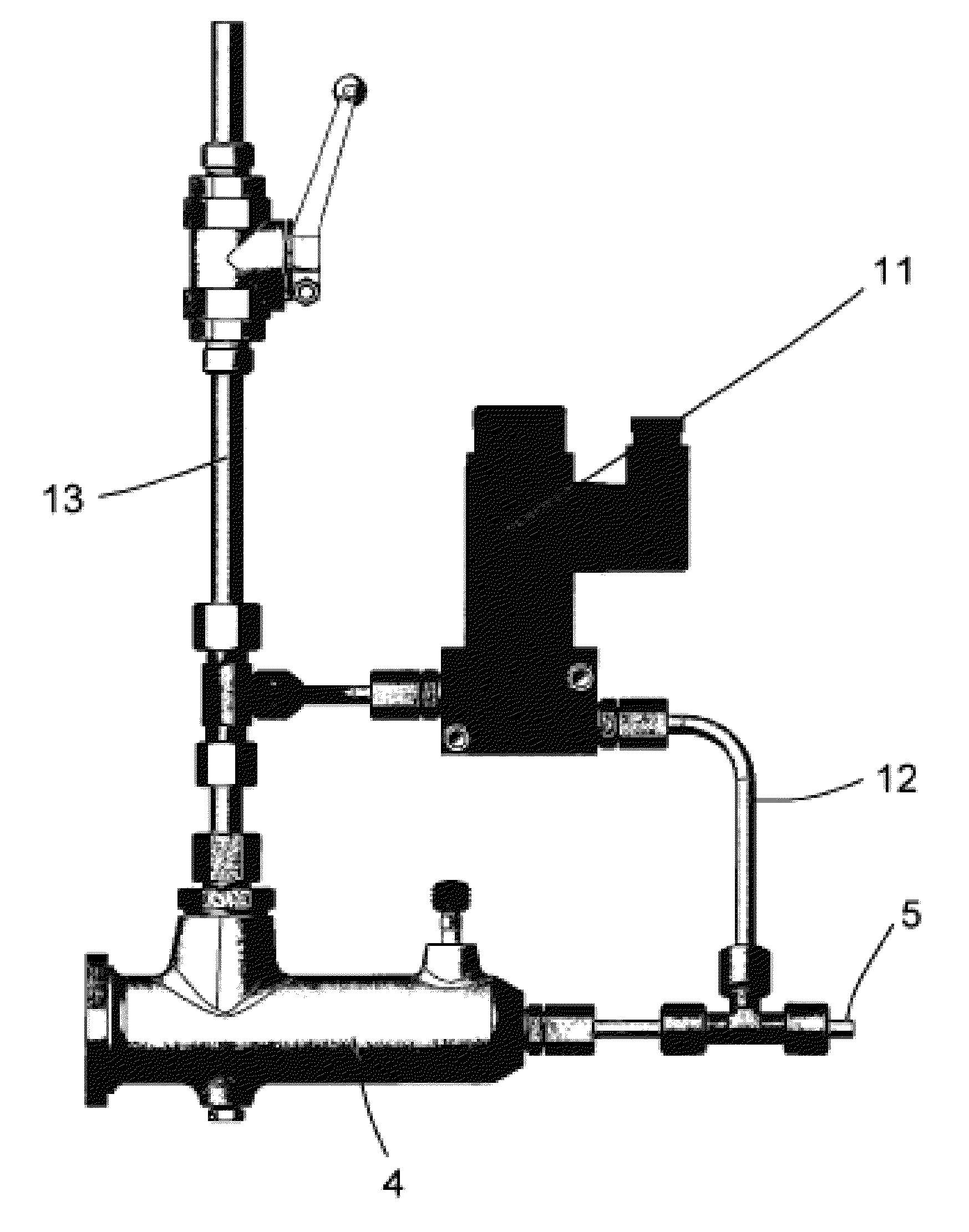
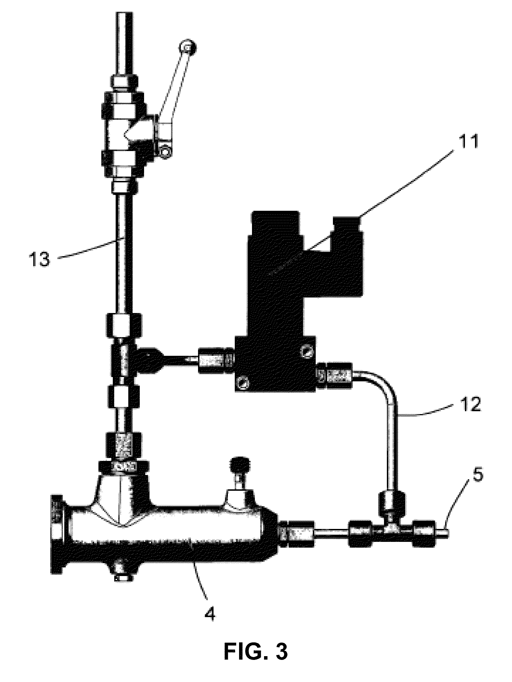
[0027]This variant is advantageous because it is always possible to completely relieve the pressure in the brake system. An advantage of a classical hydraulical actuation in the primary circuit (brake actuator side) is the easy and reliable treatment of failures. In the event of a failure, the pressure in the primary circuit should always be completely relieved or at least be reduced, in order to be able to accordingly decrease the brake pressure on the secondary side as well. This is to ensure that, for example, the load can be removed from an overheating vehicle brake within a very short time, in order to protect the brake. In a hydraulically configured primary circuit, it is always possible to achieve an easy and immediate reduction of the pressure in the secondary circuit of the brake system if the pump provided for generating the supply pressure in the primary circuit can be switched off. If, however, an electrically driven brake actuator is provided in the primary circuit—as it is described herein—it is not possible to relieve the pressure spontaneously. Due to the friction in the mechanical components (electric motor, planetary roller screw drive), the pressure on the primary side, i.e. the pressure acting on the brake master cylinder, cannot be relieved at the desired rate. Even if the electric current for the electric motor is switched off, there will still always remain a significant residual pressure in the system. For this reason, the bypass valve described above, which is disposed in parallel to the brake master cylinder and can be switched by the test bench control, is suggested. In the event of the brake application being turned off, it is therefore possible to spontaneously depressurize the brake system (secondary circuit) without the encoder (brake actuator, primary side) at the brake master cylinder having to be completely moved out of the cylinder and a bottom check valve present in the brake master cylinder opening.
[0038]Only then will the bypass valve be closed—through a command of the test bench control —with the result that the actual brake application can start.
[0040]In this manner, reproducible conditions are achieved in the secondary circuit (braking circuit). Due to the presence of the bottom check valve, this method allows leveling even low pressures in case of thermally demanding brake applications (expansion of the brake fluid medium because the brake is heated, for example in case of a long-term brake application to simulate downhill drives) in a reliable and safe manner. Furthermore, reproducible test brake applications are possible by means of a defined position of the bottom check valve without still having to deform seals or rubber elements in the brake master cylinder during the actual build-up of pressure (after the bottom check valve has closed), which seals or rubber elements would impair or at least alter the build-up of pressure.

Problems solved by technology

In these systems, considerable complexity in terms of construction (special valves, friction-reduced and force-lubricated cylinders) is required to achieve particularly the dynamics mentioned above (high pressure gradient).

Method used


Image

  • Brake test bench having an electrical brake actuator and method for same
  • Brake test bench having an electrical brake actuator and method for same
  • Brake test bench having an electrical brake actuator and method for same

Examples


Embodiment Construction

[0048]As required, detailed embodiments of the present invention are disclosed herein; however, it is to be understood that the disclosed embodiments are merely exemplary of the invention, which can be embodied in various forms. Therefore, specific structural and functional details disclosed herein are not to be interpreted as limiting, but merely as a basis for the claims and as a representative basis for teaching one skilled in the art to variously employ the present invention in virtually any appropriately detailed structure. Further, the terms and phrases used herein are not intended to be limiting; but rather, to provide an understandable description of the invention. While the specification concludes with claims defining the features of the invention that are regarded as novel, it is believed that the invention will be better understood from a consideration of the following description in conjunction with the drawing figures, in which like reference numerals are carried forwar...


PUM

PropertyMeasurementUnit
pressure gradientaaaaaaaaaa
hydraulic pressureaaaaaaaaaa
pressureaaaaaaaaaa

Abstract

A test bench for testing a brake comprises a pressure generating assembly for providing a brake fluid with an increased hydraulic pressure, a test bench control, and an electromechanical brake actuator. The pressure generating assembly is actuated mechanically and the brake fluid is supplied to the brake to actuate the brake. The electromechanical brake actuator, which simulates a vehicle driver's braking foot, is provided for mechanical actuation of the pressure generating assembly. The brake actuator comprises an electric motor activated by the test bench control and a planetary roller screw drive driven by the electric motor. The planetary roller screw drive is mechanically coupled to the pressure generating assembly to mechanically actuate the pressure generating assembly.

Description

CROSS-REFERENCE TO RELATED APPLICATIONS[0001]This application is a continuing application, under 35 U.S.C. §120, of copending international application No. PCT / EP2011 / 002535, filed May 20, 2011, which designated the United States and was not published in English; this application also claims the priority, under 35 U.S.C. §119, of German Patent Application No. 10 2010 024 336.1, filed Jun. 18, 2010; the prior applications are herewith incorporated by reference in their entirety.STATEMENT REGARDING FEDERALLY SPONSORED RESEARCH OR DEVELOPMENT[0002]Not ApplicableFIELD OF THE INVENTION[0003]The present invention lies in the field of brakes. The present disclosure relates to a brake test bench having an electrical brake actuator and a method for improving the repeat accuracy of the simulated brake applications.BACKGROUND OF THE INVENTION[0004]Brake test benches serve to test, in particular, vehicle brakes, for example, with regard to wear and tear, coefficient of friction, noise emission,...

Claims


Application Information

Patent Timeline
Patent Type & Authority Patents(United States)
IPC IPC(8): B60T17/22G01L5/28F16H25/22
CPCB60T17/221G01L5/28B60T2270/406F16H25/2252
Inventor GERMANN, STEFAN
Owner HORIBA EURO
Learn More