
Oscillator circuit and configuration method thereof

a technology of oscillator circuit and configuration method, which is applied in the direction of oscillator generator, pulse automatic control, electrical apparatus, etc., can solve the problems of low output frequency accuracy, and high production cost of circuits, and achieve low output frequency accuracy and high cost

Active Publication Date: 2016-04-05
SEMICON MFG INT (SHANGHAI) CORP
View PDF2 Cites 0 Cited by
  • Summary
  • Abstract
  • Description
  • Claims
  • Application Information

AI Technical Summary

Benefits of technology

The present invention aims to solve the problems of low output frequency accuracy and high production cost associated with currently available oscillator circuits. The invention proposes a method and system to improve the accuracy of low-cost oscillator circuits while reducing the production cost of high-accuracy oscillator circuits.

Problems solved by technology

As can be seen, among the three most commonly used oscillator circuits, RC oscillator circuits and ring oscillator circuits have relatively low production cost, but have low output frequency accuracy.
Crystal oscillator circuits have high output frequency accuracy, but also have high production cost.

Method used


Image

  • Oscillator circuit and configuration method thereof
  • Oscillator circuit and configuration method thereof
  • Oscillator circuit and configuration method thereof

Examples


Embodiment Construction

[0018]Reference will now be made in detail to exemplary embodiments of the invention, which are illustrated in the accompanying drawings. Hereinafter, embodiments consistent with the disclosure will be described with reference to drawings. Wherever possible, the same reference numbers will be used throughout the drawings to refer to the same or like parts. It is apparent that the described embodiments are some but not all of the embodiments of the present invention. Based on the disclosed embodiment, persons of ordinary skill in the art may derive other embodiments consistent with the present disclosure, all of which are within the scope of the present invention.

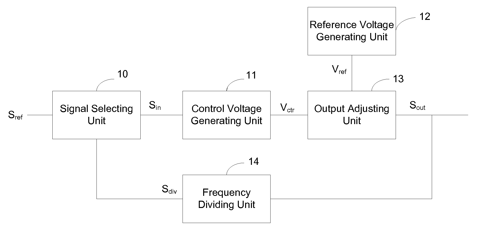
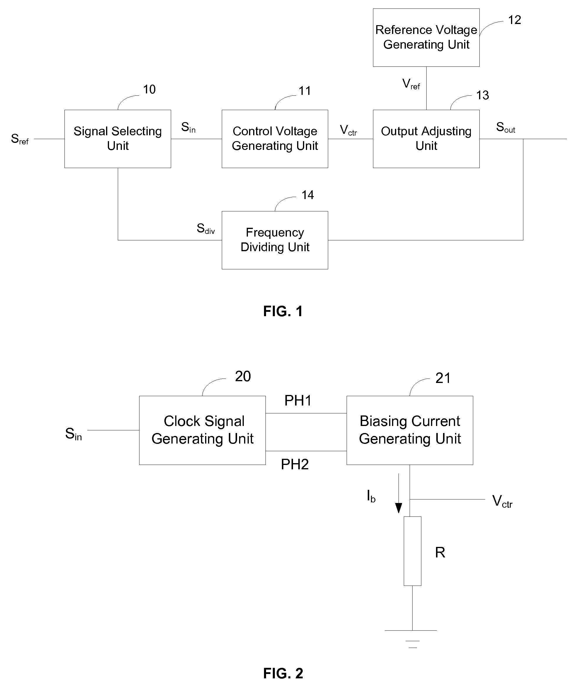
[0019]To reduce production cost and to improve output frequency accuracy of oscillator circuits, the present disclosure provides an oscillator circuit. The oscillator circuit may include a closed-loop circuit in order to control and correct the output frequency of the circuit in real time. Thus, the frequency of the output s...


PUM


Abstract

The present disclosure provides an oscillator circuit. The oscillator circuit includes a signal selecting unit, a control voltage generating unit, a reference voltage generating unit, an output adjusting unit, and a frequency-dividing unit. The signal selecting unit is configured to select a reference signal or a frequency-divided signal as an input signal. The control voltage generating unit is configured to generate a control voltage based on the input signal. The reference voltage generating unit is configured to generate a reference voltage. The output adjusting unit is configured to generate an output signal based on the control voltage and the reference voltage. The frequency-dividing unit is configured to divide the frequency of the output signal and generate the frequency-divided signal.

Description

CROSS-REFERENCES TO RELATED APPLICATIONS[0001]This application claims the priority of Chinese Patent Application No. 201410230774.3, filed on May 28, 2014, the entire content of which is incorporated herein by reference.ART OF THE DISCLOSURE[0002]The present disclosure generally relates to the field of integrated circuit (IC) technology and, more particularly, relates to oscillator circuit.BACKGROUND[0003]An oscillator is an electronic device that can produce a periodic, oscillating electronic signal. A circuit with an oscillator is called an oscillator circuit. There are many types of oscillators. For example, categorized by the method of excitation, there are self-excited oscillators and separately excited oscillators. Categorized by the circuit structure, there are RC (resistor-capacitor) oscillators, LC (resistor-inductor) oscillators, crystal oscillators, and ring oscillators, and tuning fork oscillators. Further, categorized by the output waveform, there are sine-wave oscillat...

Claims


Application Information

Patent Timeline
Patent Type & Authority Patents(United States)
IPC IPC(8): H03L7/24H03B5/24H03B5/12
CPCH03B5/12H03B5/24H03L7/24H03L7/00
Inventor FU, ZHIGANG
Owner SEMICON MFG INT (SHANGHAI) CORP
Learn More