Radio frequency antenna assembly for hydrocarbon resource recovery including adjustable shorting plug and related methods

a radio frequency antenna and hydrocarbon resource technology, applied in the direction of individual energised antenna arrays, well accessories, insulation, etc., can solve the problems of increasing energy consumption worldwide, reducing the service life of the antenna array, so as to achieve the effect of improving the operating characteristics

Active Publication Date: 2016-04-12
HARRIS CORP
View PDF20 Cites 0 Cited by
  • Summary
  • Abstract
  • Description
  • Claims
  • Application Information

AI Technical Summary

Benefits of technology

[0013]These and other objects, features, and advantages are provided by a radio frequency (RF) antenna assembly designed to be positioned within a wellbore in a subterranean formation for hydrocarbon resource recovery that includes an RF transmission line and an RF antenna coupled to the RF transmission line. The RF antenna assembly also includes an adjustable balun that includes a tubular balun housing surrounding the RF transmission line and defining a space therebetween. The adjustable balun further includes an adjustable shorting body slidably movable within the space and contacting the tubular balun housing and the RF transmission line at an adjustable shorting position. Accordingly, the balun may advantageously reduce common mode currents on the RF transmission line, for example, the an outer conductor of the RF transmission line, as the operating characteristics of the antenna change during the heating process to thereby provide enhanced efficiencies.

Problems solved by technology

Energy consumption worldwide is generally increasing, and conventional hydrocarbon resources are being consumed.
For example, highly viscous hydrocarbon resources, such as heavy oils, may be trapped in tar sands where their viscous nature does not permit conventional oil well production.
The SAGD process may be relatively sensitive to shale streaks and other vertical barriers since, as the rock is heated, differential thermal expansion causes fractures in it, allowing steam and fluids to flow through.
Oil is not yet produced from oil sands on a significant level in other countries.
Unfortunately, long production times, for example, due to a failed start-up, to extract oil using SAGD may lead to significant heat loss to the adjacent soil, excessive consumption of steam, and a high cost for recovery.
Limited water resources may also limit oil recovery.
SAGD is also not an available process in permafrost regions, for example.
Moreover, despite the existence of systems that utilize RF energy to provide heating, such systems may suffer from inefficiencies as a result of impedance mismatches between the RF source, transmission line, and / or antenna.
These mismatches become particularly acute with increased heating of the subterranean formation.
Moreover, such applications may require high power levels that result in relatively high transmission line temperatures that may result in transmission failures.
This may also cause problems with thermal expansion as different materials may expand differently, which may render it difficult to maintain electrical and fluidic interconnections.

Method used


Image

  • Radio frequency antenna assembly for hydrocarbon resource recovery including adjustable shorting plug and related methods
  • Radio frequency antenna assembly for hydrocarbon resource recovery including adjustable shorting plug and related methods
  • Radio frequency antenna assembly for hydrocarbon resource recovery including adjustable shorting plug and related methods

Examples


Embodiment Construction

[0021]The present invention will now be described more fully hereinafter with reference to the accompanying drawings, in which preferred embodiments of the invention are shown. This invention may, however, be embodied in many different forms and should not be construed as limited to the embodiments set forth herein. Rather, these embodiments are provided so that this disclosure will be thorough and complete, and will fully convey the scope of the invention to those skilled in the art. Like numbers refer to like elements throughout.

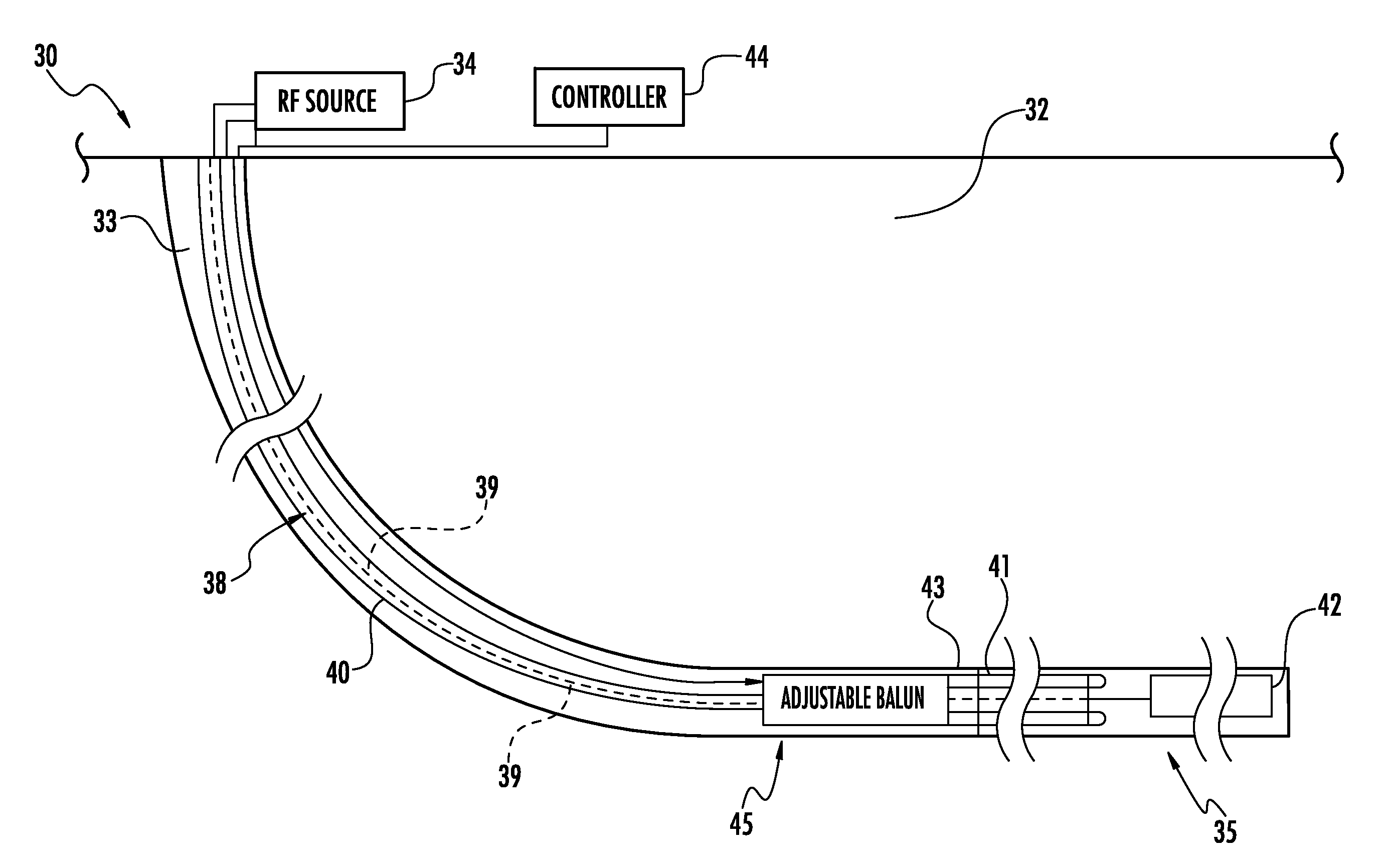
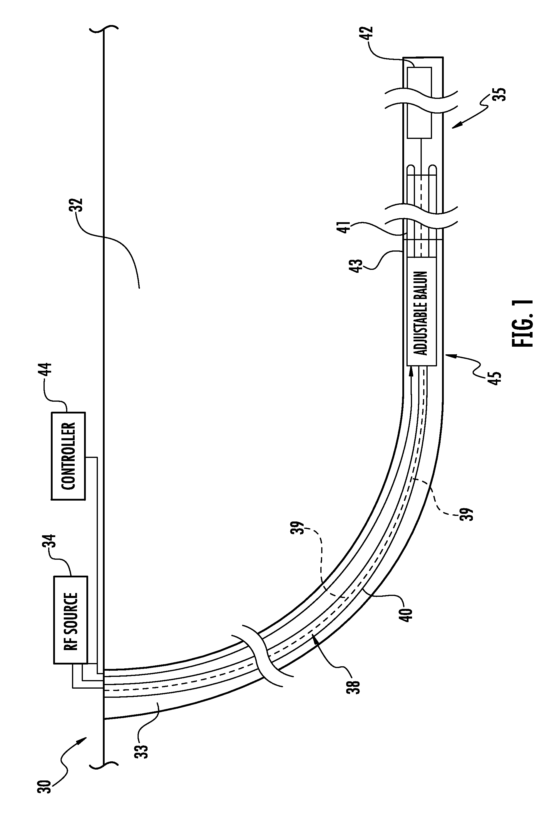
[0022]Referring initially to FIG. 1, an apparatus 30 for heating a hydrocarbon resource (e.g., oil sands, etc.) in a subterranean formation 32 having a wellbore 33 therein is described. In the illustrated example, the wellbore 33 is a laterally extending wellbore, although the system 30 may be used with vertical or other wellbores in different configurations. The system 30 further illustratively includes a radio frequency (RF) source 34 for an RF antenna o...


PUM


Abstract

A radio frequency (RF) antenna assembly configured to be positioned within a wellbore in a subterranean formation for hydrocarbon resource recovery may include an RF transmission line and an RF antenna coupled to the RF transmission line. The RF antenna assembly may also include an adjustable balun that may include a tubular balun housing surrounding the RF transmission line and defining a space therebetween. The adjustable balun may further include an adjustable shorting body slidably movable within the space and contacting the tubular balun housing and the RF transmission line at an adjustable shorting position.

Description

FIELD OF THE INVENTION[0001]The present invention relates to the field of hydrocarbon resource recovery, and, more particularly, to hydrocarbon resource recovery using RF heating.BACKGROUND OF THE INVENTION[0002]Energy consumption worldwide is generally increasing, and conventional hydrocarbon resources are being consumed. In an attempt to meet demand, the exploitation of unconventional resources may be desired. For example, highly viscous hydrocarbon resources, such as heavy oils, may be trapped in tar sands where their viscous nature does not permit conventional oil well production. Estimates are that trillions of barrels of oil reserves may be found in such tar sand formations.[0003]In some instances these tar sand deposits are currently extracted via open-pit mining. Another approach for in situ extraction for deeper deposits is known as Steam-Assisted Gravity Drainage (SAGD). The heavy oil is immobile at reservoir temperatures and therefore the oil is typically heated to reduce...

Claims


Application Information

Patent Timeline
Patent Type & Authority Patents(United States)
IPC IPC(8): H05B6/64E21B36/00H01Q21/12E21B43/24
CPCE21B43/2401H01P5/08H01Q1/50H01Q9/16
Inventor WRIGHT, BRIANHANN, MURRAYHEWIT, RAYMONDHIBNER, VERLIN A.
Owner HARRIS CORP
Why Eureka
Try Eureka