Methods and systems for providing or maintaining fluid flow through body passages

a technology of body passages and fluid flow, applied in blood vessels, prostheses, catheters, etc., can solve the problems of significant surgical trauma, conventional coronary bypass surgery is not always an option, balloon angioplasty is not always a suitable measure, etc., and achieve the effect of improving the targeting and localization of therapy administration

Active Publication Date: 2016-04-19
LIMFLOW
View PDF168 Cites 42 Cited by
  • Summary
  • Abstract
  • Description
  • Claims
  • Application Information

AI Technical Summary

Benefits of technology

[0009]The present application provides methods and systems for overcoming certain deficiencies and / or improving percutaneous methods and systems. For example, according to several embodiments, the methods and systems described herein can improve targeting and localization of therapy administration, which may advantageously provide treatment via percutaneous techniques to patients unsuitable for more invasive surgery. Certain embodiments described herein can provide fluid flow in passages such as coronary and / or peripheral blood vessels by creating a bypass using minimally invasive percutaneous surgical techniques.
[0020]By allowing the two end portions to move relative to each other, the device can respond to movement of the passage or passages in which the device is used. The intermediate portion may be flexible to allow relative movement of the end portions. In some embodiments, the device has varying or differential flexibility along the length of the device or along a length of a portion of the device. Device flexibility can reduce the likelihood of device failure due to fatigue, for example because the magnitude of stresses within the intermediate portion may be relatively low in comparison to stresses on a support structure (e.g., stent) with uniform flexibility along its entire length.
[0023]In embodiments in which the end portions can move relative to one another by virtue of the intermediate portion, the device may be suitable for use in applications where the end portions are anchored in separate passages that move relative to one another. A pathway for fluid communication to be maintained through the device irrespective of the relative movement of the end portions, and the likelihood of fatigue failure of the device due to cyclic movement of the end portions may be low in comparison to a support structure (e.g., stent) lacking such an intermediate portion.
[0030]One or both end portions may include anchoring protuberances or barbs capable of and / or configured to dig into or grasp the inside sidewalls of a passage, for example to prevent or reduce slippage or other movement of the or each end portion relative to the passage.

Problems solved by technology

Balloon angioplasty is not always a suitable measure, for example in acute cases and in cases where a coronary artery is completely occluded.
To perform the procedure, the patient's heart must be exposed by opening the chest, separating the breastbone, and cutting the pericardium surrounding the heart, resulting in significant surgical trauma.
Conventional coronary bypass surgery is not always an option.
Certain patients are unsuitable as candidates for conventional coronary bypass surgery due low expectation of recovery or high risk from the significant trauma due to surgery, high risk of infection, absence of healthy vessels to use as bypass grafts, significant co-morbidities, and expected long and complicated recovery time associated with open-chest surgery.

Method used


Image

  • Methods and systems for providing or maintaining fluid flow through body passages
  • Methods and systems for providing or maintaining fluid flow through body passages
  • Methods and systems for providing or maintaining fluid flow through body passages

Examples


example

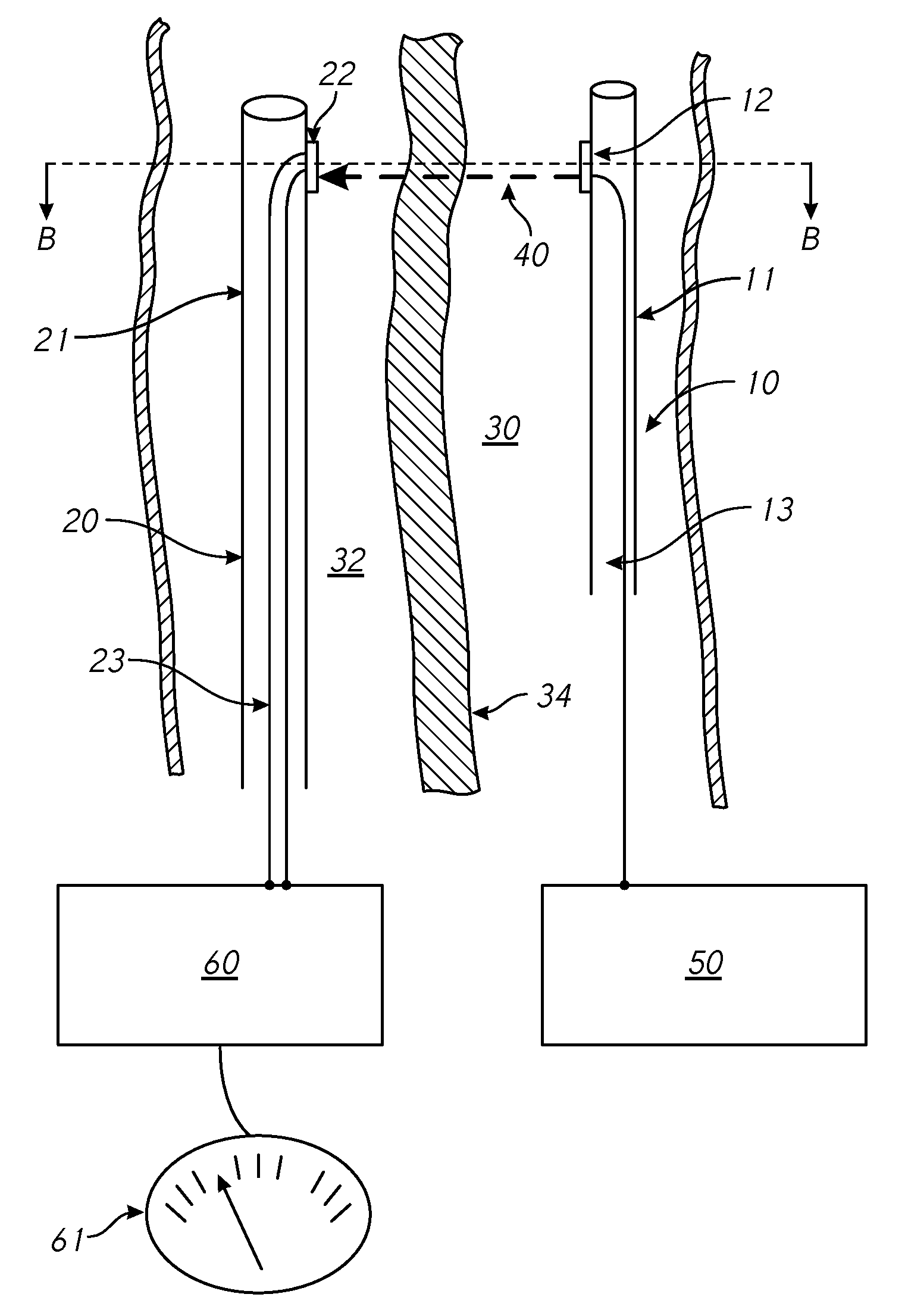
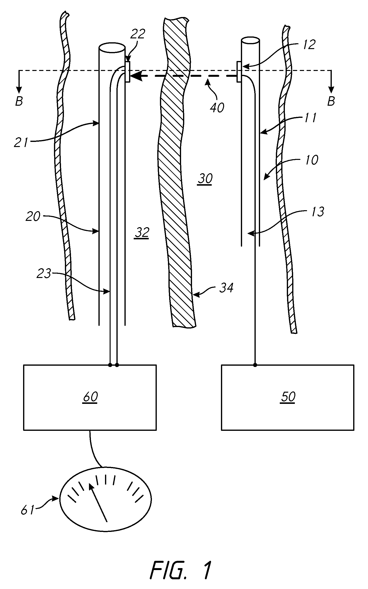
[0118]The methods and systems described herein demonstrate particular utility in cardiovascular surgery according to several embodiments. Certain aspects are further illustrated by the following non-limiting example, in which the system is used by a clinician to perform the procedure of arterial-venous connection (PICVA) so as to enable retroperfusion of cardiac tissue following occlusion of a coronary artery.

[0119]The launching catheter 10 is inserted into the occluded coronary artery by standard keyhole surgical techniques (e.g., tracking over a guidewire, tracking through a guide catheter). The target catheter 20 is inserted into the coronary vein that runs parallel to the coronary artery by standard keyhole surgical techniques (e.g., tracking over a guidewire, tracking through a guide catheter). The coronary vein is not occluded and, therefore, provides an alternative channel for blood flow to the cardiac muscle, effectively allowing the occlusion in the coronary artery to be by...


PUM


Abstract

A device includes a first end portion, a second end portion, an intermediate portion, and a graft material. The first end portion has a first end diameter. The second end portion has a second end diameter smaller than the first end diameter. The first end portion comprises a first material. The second end portion comprises a second material different than the first material. The intermediate portion is between the first end portion and the second end portion. The intermediate portion tapers between the first end portion and the second end portion. The graft material is coupled to at least the intermediate portion.

Description

INCORPORATION BY REFERENCE[0001]This application claims the benefit under 35 U.S.C. §120 and 35 U.S.C. §365(c) as a continuation of International Application No. PCT / US2011 / 026501 designating the United States, with an international filing date of Feb. 28, 2011, which claims the benefit under 35 U.S.C. §119(e) of U.S. Provisional Patent App. No. 61 / 901,753, filed on Nov. 8, 2013, and International Application No. PCT / US2011 / 026501 is a continuation-in-part of U.S. patent application Ser. No. 13 / 791,185, filed on Mar. 8, 2013, each of which is hereby incorporated by reference in its entirety. U.S. patent application Ser. No. 11 / 662,128, filed on Jan. 3, 2008, U.S. patent application Ser. No. 14 / 141,913, filed on Dec. 27, 2013, and U.S. patent application Ser. No. 12 / 297,498, filed on Feb. 25, 2009 as a national phase of PCT / GB2007 / 001430, filed Apr. 20, 2007, and issued as U.S. Pat. No. 8,439,963 on May 14, 2013, are hereby incorporated by reference in their entirety.BACKGROUND[0002]...

Claims


Application Information

Patent Timeline
Patent Type & Authority Patents(United States)
IPC IPC(8): A61F2/07A61F11/00A61M27/00A61B17/11A61F2/95A61F2/844A61B17/22A61F2/06
CPCA61F2/07A61B17/11A61B17/22A61F2/844A61F2/95A61M27/002A61B2017/1107A61B2017/1139A61B2017/22097A61F2002/068A61F2230/0067A61F2230/0069A61B17/3478A61B18/245A61F2/064A61F2/90A61B8/0841A61B8/12A61B18/1492A61B2017/00252A61B2017/22095A61F2/962A61F2/915A61F2250/001A61F2250/0017A61F2250/0031A61F2250/0029A61F2250/0039A61B2034/2063A61B2017/1103A61F2/958
Inventor DICKINSON, ROBERT JULIANFERRARESI, ROBERTOKUM, STEVENLENIHAN, TIMOTHYPACEY, ANDREW ROBERTROTHMAN, MARTIN TERRY
Owner LIMFLOW
Why Eureka
Try Eureka