
Modular rapid development system for building underwater robots and robotic vehicles

a robotic vehicle and modular technology, applied in the field of autonomous underwater robots, can solve the problems of commercial underwater robotic systems exceeding the budgets of the majority of potential users of underwater robotic systems, the least expensive commercial system, and the existence of potential users for these potential users

Active Publication Date: 2016-04-19
WILLIAMS EDDIE HUGH
View PDF25 Cites 21 Cited by
  • Summary
  • Abstract
  • Description
  • Claims
  • Application Information

AI Technical Summary

Benefits of technology

The invention describes a system for underwater pressure vessels that has several improvements. These include a dry end cap with a groove for a seal, an o-ring seal, an external portion with mounting holes for components, link struts, and tube mounting holes for pressure vessels. The system has a simple design and is suitable for various underwater applications. Its technical effects include improved sealing, improved stability, and easy assembly of components.

Problems solved by technology

The primary users of these robots are the sub-sea oil and gas companies, whose profits may justify the robots' high cost.
But even at the “low end” those commercial underwater robotic systems exceed the budgets of the majority of potential users of underwater robotic systems.
A second problem exists for these potential users.
The least expensive of the commercial systems tend to be single purpose vehicles of very simple design and thus the least flexible in terms of configuration.
But no commercially available Underwater Robotic System offers its users freedom of choice, at a modular level, over the mechanical configuration of their system (e.g., how many thrusters for degrees of freedom of locomotion), what computational hardware is used to control the system (e.g., a full-function Intel-based computer running either Windows or Linux or a small 8 or 16-bit microcontroller) and whether that processor is programmed in C, Java, Python, or another language.
No inexpensive ‘build-by-menu and reconfigure-at-will’ underwater robotic solution exists for those who need broad freedom in design and configuration.
As a result, most potential users of underwater tele-presence robots who need a cheap, simple, easily re-configured system must currently design and build their own underwater robotic system from scratch; this is difficult for even experienced researchers and usually prohibitively so for the inexperienced.
While such a do-it-yourself method allows the system to be tailored exactly to the mission requirements at hand, costs can easily exceed the those of a comparable commercial system when design and test time spent dealing with the inadequacies of a leaky, unreliable prototype are factored in.
And unless modularity, extendibility, and re-configurability are carefully thought out and designed into the prototype, these scratch-built systems usually fail to provide the flexibility for expansion and re-configuration that the user will soon wish for to meet new performance requirements or to attach new payloads.

Method used


Image

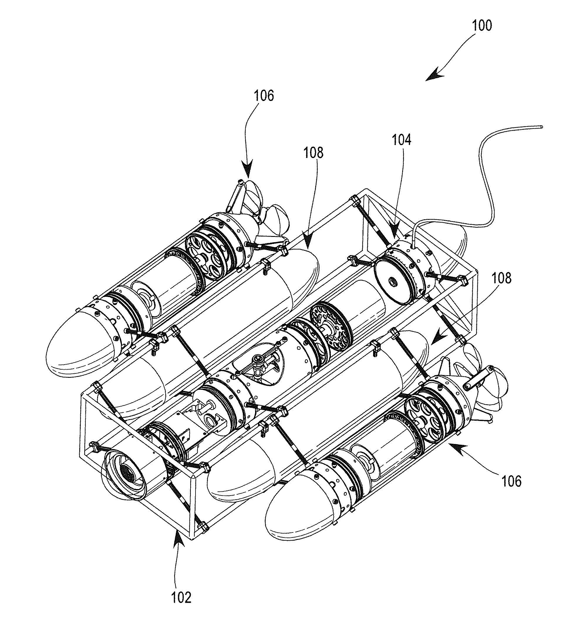
  • Modular rapid development system for building underwater robots and robotic vehicles
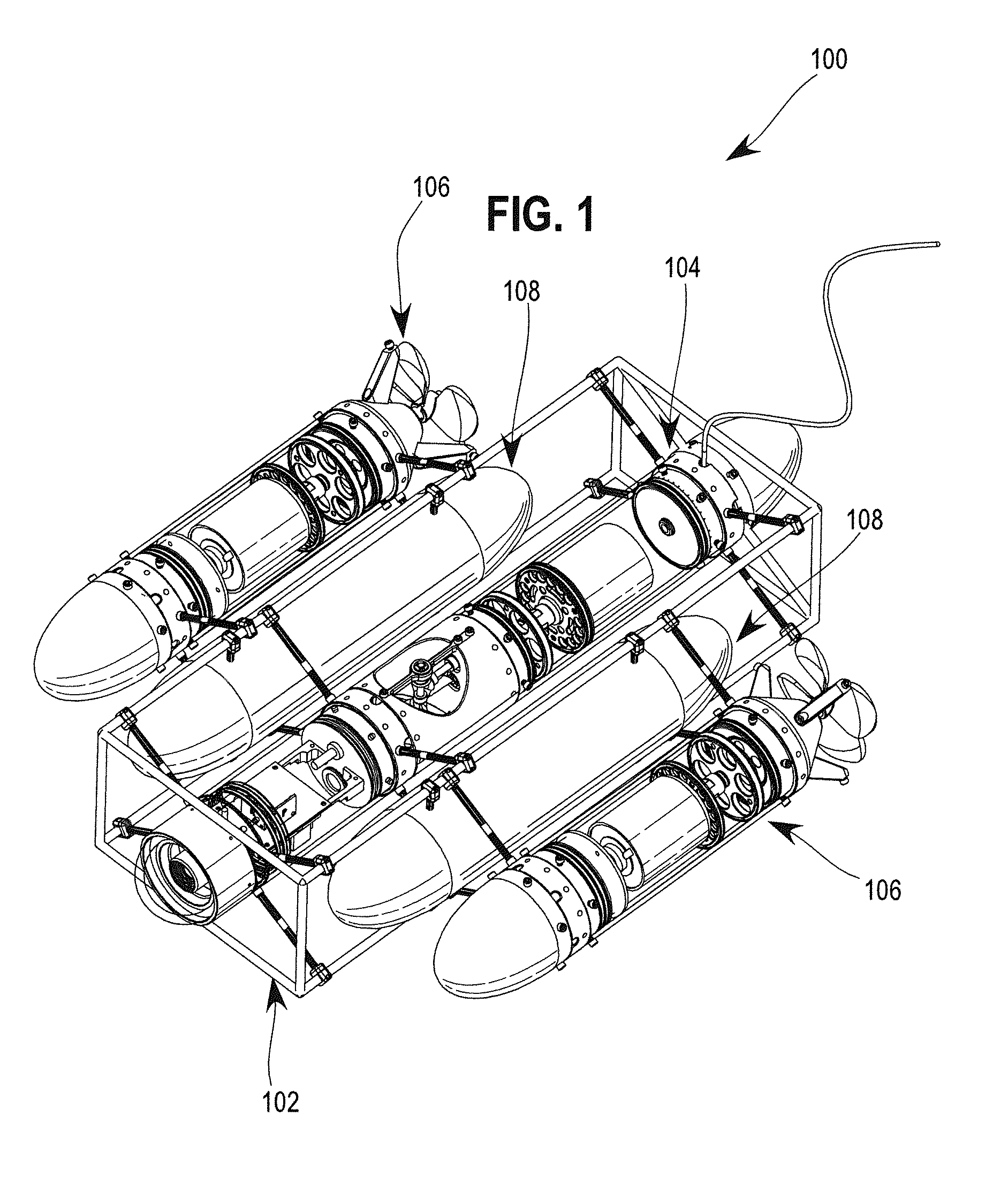
  • Modular rapid development system for building underwater robots and robotic vehicles
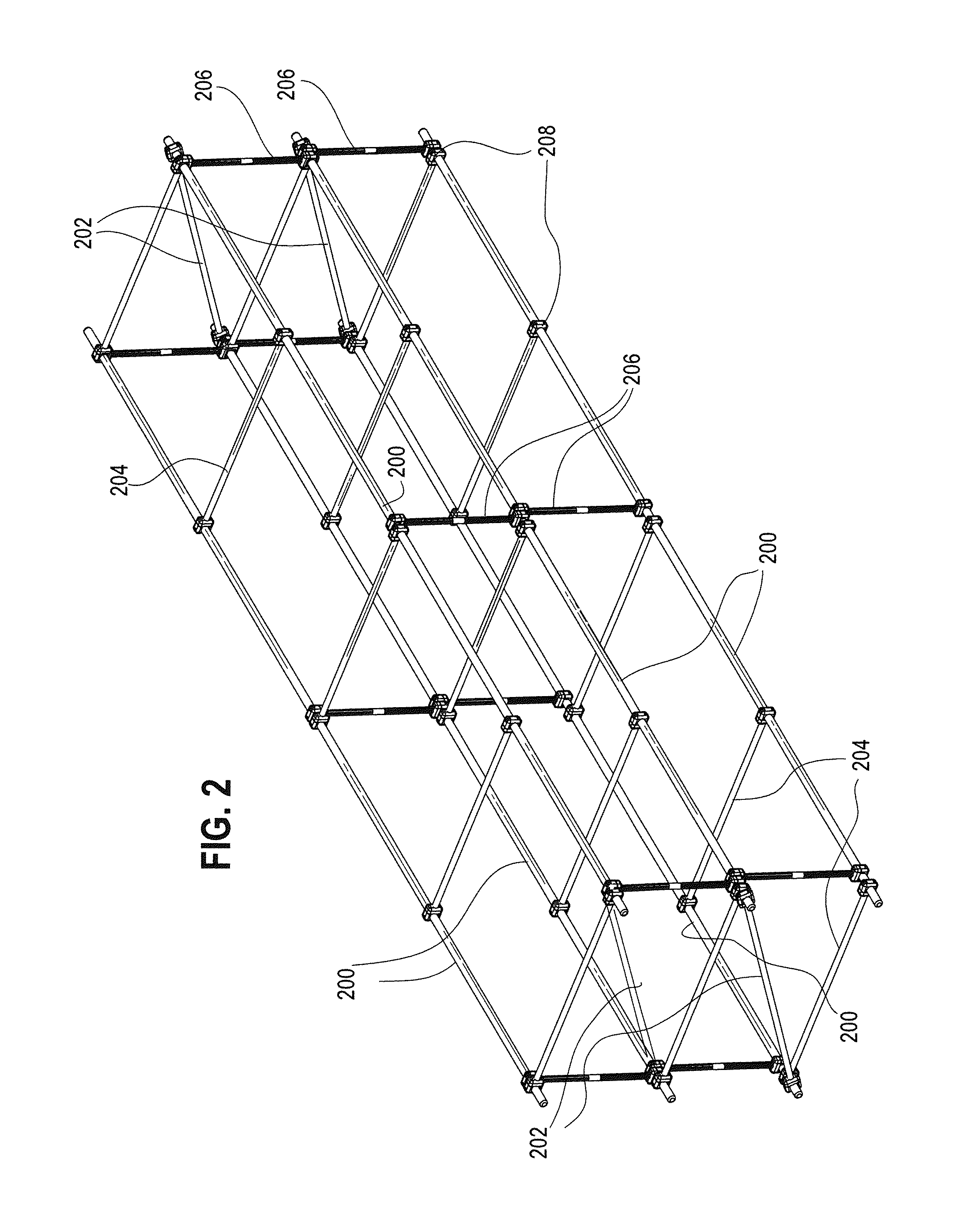
  • Modular rapid development system for building underwater robots and robotic vehicles

Examples


first embodiment

[0291]Referring next to FIG. 42, the mounting clip 4200 in a first embodiment is shown. Shown are a clip U-shaped portion 4202, two prongs 4204, a washer 4206, a nut 4208, and a clip threaded fastener 4210.

[0292]The mounting clip 4200 comprises the generally U-shaped portion 4202 (with the prongs 4204 of the U-shape oriented downward) including two rounded prongs 4204 configured to snap around the support column rail 2906 (or other longitudinal rod member), coupling the mounting clip 4200 to the support column rail 2906. A base of the U-shape is configured to allow for the nut 4208 to fit between the prongs 4204 at the base of the U-shaped portion 4202. The optional insulated washer 4206 is located on the outside face of the base of the U-shaped portion 4202. The base of the U-shaped portion 4202 includes a hole for the clip threaded fastener 4210, which passes through the washer 4206, base of the U-shaped portion 4202 and the nut 4208, thus coupling the clip assembly together. In u...

second embodiment

[0294]Referring next to FIG. 43, the mounting clip 4200 is shown. Shown are the U-shaped portion 4202, the clip threaded fastener 4210, the nut 4208, and the prongs 4204.

[0295]In the embodiment shown in FIG. 43, a head of the clip threaded fastener 4210 is located between the prongs 4204 of the u-shape, with a shaft of the clip threaded fastener 4210 oriented in the upward direction. The nut 4208 is coupled to the clip threaded fastener 4210 above the base of the U-shape. The base of the U-shape is configured to accommodate the head of the clip threaded fastener 4210 between the prongs 4204 instead of the nut 4208 as shown in FIG. 43. The prongs 4204 are shaped similarly the embodiment shown in FIG. 42, being configured to snap onto the support column rail 2906. As with the embodiment shown in FIG. 42, in use the prongs 4204 are snapped onto the support column rail 2906, and the rectangular PCB 3900 is coupled to the mounting clip 4200 using the clip threaded fastener 4210 and the n...


PUM


Abstract

A modular system for building underwater robotic vehicles (URVs), including a pressure vessel system, modular chassis elements, a propulsion system and compatible buoyancy modules. The pressure vessel system uses standardized, interchangeable modules to allow for ease of modification of the URV and accommodation of different internal and external components such as sensors and computer systems. The system also includes standard, reconfigurable connections of the pressure vessel to the modular chassis system. A standardized, modular propulsion system includes a magnetic clutch, and a magnetic sleeve used to power the URV on or off.

Description

[0001]This application claims the benefit of U.S. Provisional Application No. 61 / 881,894, filed Sep. 24, 2013, for MODULAR RAPID DEVELOPMENT SYSTEM FOR BUILDING UNDERWATER ROBOTS AND ROBOTIC VEHICLES, which is incorporated in its entirety herein by reference.BACKGROUND OF THE INVENTION[0002]1. Field of the Invention[0003]The present invention relates generally to autonomous underwater robots, and more specifically, to systems and methods for building autonomous underwater robots and remotely piloted underwater robotic vehicles[0004]2. Discussion of the Related Art[0005]Just as robotic vehicles have proven their effectiveness as an alternative to manned space exploration, researchers in Oceanography, Sub-Sea Oil and Gas and Mineral Production, Fisheries Management, Marine Environmental Pollution Management, Marine Biological Diversity Surveys, Marine Salvage, Underwater Search and Rescue, and other related fields have found underwater robotic vehicles an effective alternative to send...

Claims


Application Information

Patent Timeline
Patent Type & Authority Patents(United States)
IPC IPC(8): B63G8/00B25J9/08B63B3/13B63B9/06B63G8/08
CPCB25J9/08B63B3/13B63G8/001B63G8/08B63G2008/005B63B73/20B63B73/40Y10S901/01
Inventor WILLIAMS, EDDIE HUGH
Owner WILLIAMS EDDIE HUGH
Learn More