Electronic thermometer and method for manufacturing the same

a technology of electronic thermometers and thermometers, applied in the field of electronic thermometers, can solve problems such as the decrease of measurement precision, and achieve the effects of suppressing bending and directional misalignment of lead, and fast thermal respons

Active Publication Date: 2016-04-19
OMRON HEALTHCARE CO LTD
View PDF26 Cites 4 Cited by
  • Summary
  • Abstract
  • Description
  • Claims
  • Application Information

AI Technical Summary

Benefits of technology

[0017]According to the present invention, it is possible to provide an electronic thermometer that is inexpensive, has fast thermal response, and suppresses bending and directional misalignment of the lead of the temperature sensor during assembly of the electronic thermometer.

Problems solved by technology

In this case, if the temperature sensor lead that extends out from the sub-case becomes bent or directionally misaligned, faults occur in which the insertion of the temperature sensor into the main housing does not go well, measurement precision decreases due to positional misalignment of the temperature sensing unit at the tip of the temperature sensor, and product variations (instrumental error) arise between individual electronic thermometers.

Method used


Image

  • Electronic thermometer and method for manufacturing the same
  • Electronic thermometer and method for manufacturing the same
  • Electronic thermometer and method for manufacturing the same

Examples


first embodiment

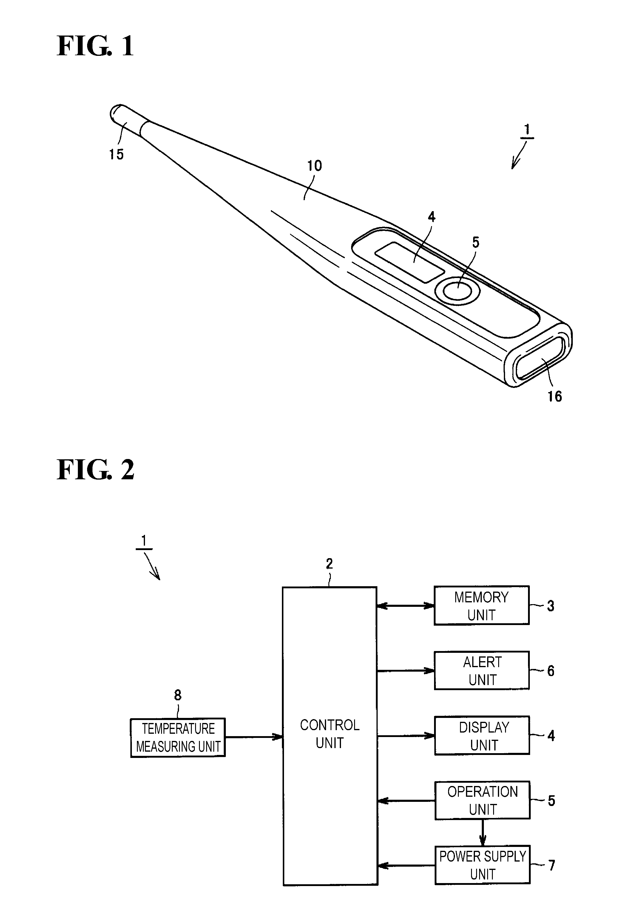
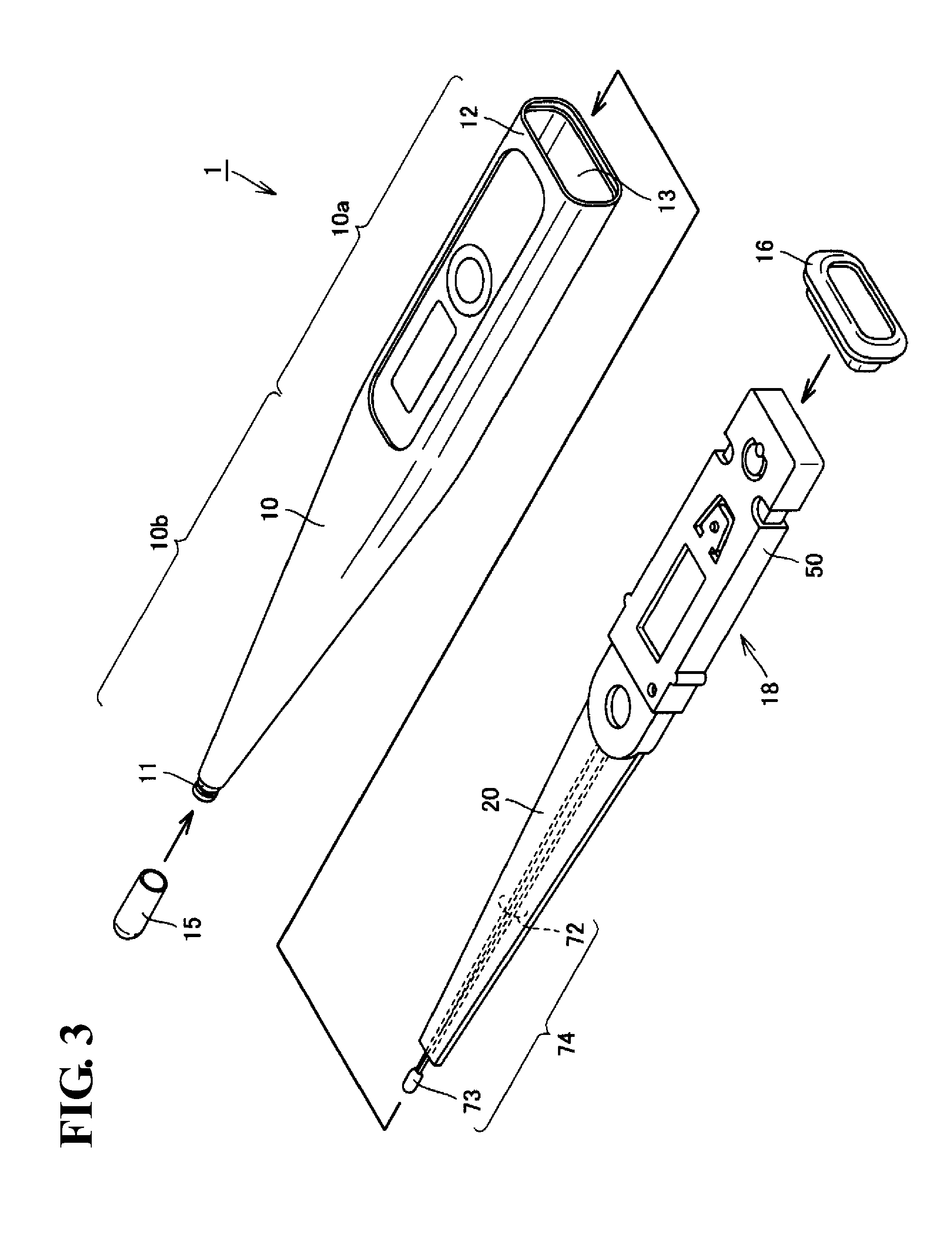
[0046]FIG. 1 is a perspective view of an external structure of an electronic thermometer 1 according to a first embodiment of the present invention, and FIG. 2 is a diagram showing a configuration of functional blocks of the electronic thermometer 1 shown in FIG. 1. First, the overall configuration of the electronic thermometer 1 of the present embodiment will be described with reference to FIGS. 1 and 2.

[0047]As shown in FIG. 1, the electronic thermometer 1 of the present embodiment includes a main housing 10, a cap 15 that forms a temperature measuring unit, and an obstructing member 16. The main housing 10 is a tubular hollow member made of a resin material such as ABS (acrylonitrile butadiene styrene) resin. The main housing 10 has a faceplate affixed at a predetermined position on its top face, and also has a display unit 4 and an operation unit 5 at predetermined positions on its top face. The cap 15 is a bottomed tube-shaped member, one end of which is obstructed. The cap 15 ...

second embodiment

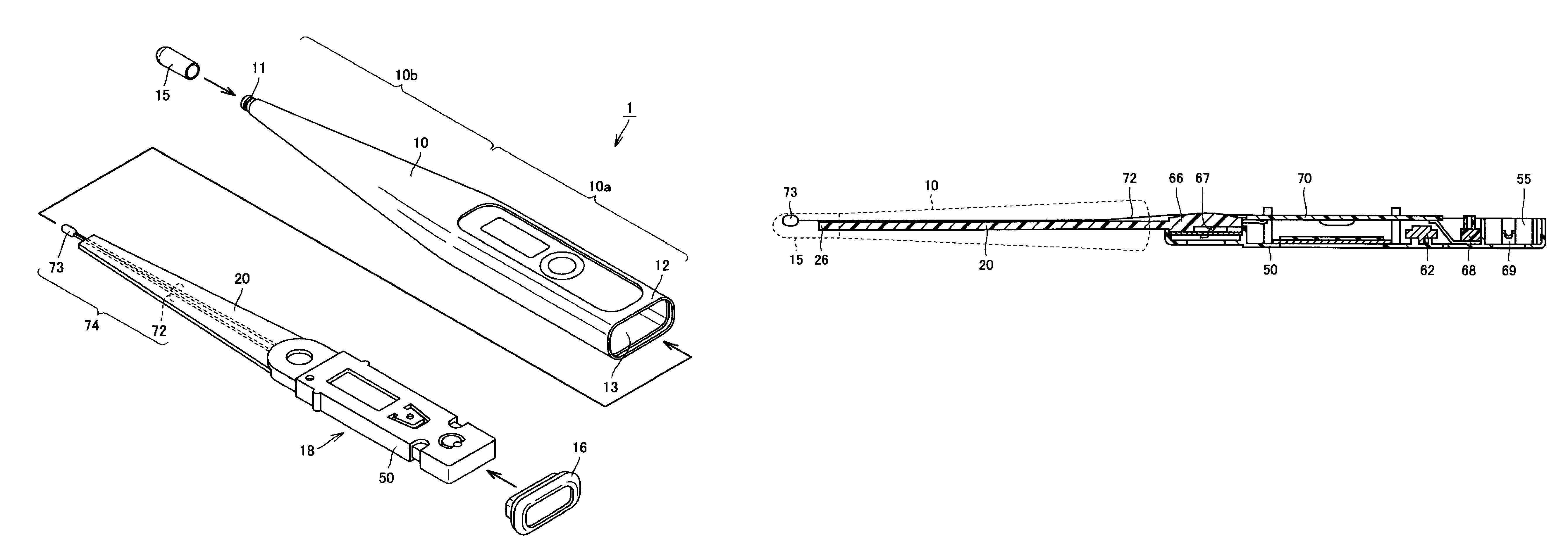
[0089]FIG. 9 is a perspective view of the internal structure of the electronic thermometer 1 according to a second embodiment. FIG. 10 is a cross-sectional view of the internal structure of the electronic thermometer 1 according to the second embodiment. The electronic thermometer 1 of the second embodiment is different from the above-described first embodiment in that the sub-case 50 of the assembly 18 extends toward the tip portion 11 side of the main housing 10 to form the extension portion 20.

[0090]Specifically, in the second embodiment, the buzzer cover 66 is formed so as to have a shape of covering the buzzer 65, and is housed inside the sub-case 50. The extension portion 20 is formed so as to extend from an outer side face of the front end portion of the sub-case 50 in the lengthwise direction. The extension portion 20 is a resin molded part, which is molded integrally with the sub-case 50 made of a resin material that is included in the assembly 18. On the extension portion ...

third embodiment

[0094]FIG. 11 is a plan view of the arrangement of the extension portion 20 and the lead 72 according to the third embodiment. FIG. 12 is a cross-sectional view of the extension portion 20 according to the third embodiment taken along line XII-XII shown in FIG. 11. As shown in FIGS. 11 and 12, a through-hole 30 that pierces the extension portion 20 in the thickness direction is provided in the extension portion 20 of the third embodiment. The through-hole 30 is formed so as to extend along the extending direction of the extension portion 20. The lead 72 is arranged so as to extend beyond the through-hole 30.

[0095]As shown in FIG. 12, the fixing material 41 of the third embodiment is provided on the top face 21 of the extension portion 20 at a position on the projecting end 26 side relative to the through-hole 30. The fixing material 41 is arranged at a position that opposes the base part where the extension portion 20 projects from the assembly 18, with the through-hole 30 interpose...


PUM

PropertyMeasurementUnit
thicknessaaaaaaaaaa
body temperatureaaaaaaaaaa
temperatureaaaaaaaaaa

Abstract

Provided is an electronic thermometer that is inexpensive, has fast thermal response, and suppresses bending and directional misalignment of the lead of the temperature sensor during assembly of the electronic thermometer. The electronic thermometer includes: a temperature sensor that includes a temperature sensing unit that measures the body temperature of a measurement subject and a lead having one end that is fixed to the temperature sensing unit; a hollow housing that houses the lead, and in which the temperature sensing unit is arranged on the tip side; a printed circuit board to which the other end of the lead is fixed; and an assembly that includes the printed circuit board and is housed in the housing. The assembly includes an extension portion extending toward the tip side of the housing. The extension portion has a guide portion that orients the extending direction of the lead.

Description

[0001]This is a Continuation of Application No. PCT / JP2011 / 065979 filed Jul. 13, 2011, which in turn is a National Phase of Japanese Application No. 2010-209226 filed Sep. 17, 2010. The disclosure of the prior applications is hereby incorporated by reference herein in its entirety.TECHNICAL FIELD[0002]The present invention relates to an electronic thermometer and a method for manufacturing the same, and in particular relates to an electronic thermometer that includes a radial lead temperature sensor and a method for manufacturing such an electronic thermometer.BACKGROUND ART[0003]In general, with an electronic thermometer for performing body temperature measurement when placed at a measurement site such as the armpit or under the tongue, a liquid crystal display, a printed circuit board, and the like are fixed in a sub-case, the sub-case is arranged inside a main housing, a temperature sensor is housed in a temperature measuring unit, and the temperature measuring unit is provided i...

Claims


Application Information

Patent Timeline
Patent Type & Authority Patents(United States)
IPC IPC(8): G01K7/00G01K13/00G01K1/08G01K1/16
CPCG01K7/00G01K1/16G01K13/002Y10T29/49117G01K13/20
Inventor HASEGAWA, GAKUMATSUMOTO, NAOKIYAMAUCHI, TAKANOBUKAWANO, ATSUSHIFUJITA, YASUO
Owner OMRON HEALTHCARE CO LTD
Why Eureka
Try Eureka