Method and apparatus for conditioning of fracturing sand

a technology of fracturing sand and conditioning method, which is applied in the direction of drying machine, drying machine with materials at rest, light and heating apparatus, etc., can solve the problems of fracturing sand cannot be used straight from the ground, subject to conditioning, and the need for several thousand tons of sand for a single well, so as to achieve high efficiency and reduce equipment and operating costs.

Active Publication Date: 2016-04-26
INDAL ACCESSORIES
View PDF14 Cites 17 Cited by
  • Summary
  • Abstract
  • Description
  • Claims
  • Application Information

AI Technical Summary

Benefits of technology

[0015]Use of the simplified, one-pass dryer of the invention reduces both equipment and operating costs while still providing properly conditioned sand for downstream processing.

Problems solved by technology

Some subsurface rock formations, such as organic shales, contain large amounts of oil, natural gas, or natural gas liquids that will not flow freely to a well because the rock formations either lack permeability, or the pore spaces are so small that these fluids cannot readily flow through them.
A hydraulic fracturing job on a single well may require several thousand tons of sand.
However, frac sand cannot be used straight from the ground, and it must be subjected to conditioning in specialized frac sand plants.
However, such a dryer / cooler has very high horsepower requirements (e.g., 200 HP), and therefore equipment and utility costs become significant.
Such units are also sensitive to abrupt changes in solid material particle sizes, moisture content, throughput rates, and periodic cutouts of drying air.
Moreover, this type of equipment has relatively high electrical energy requirements, and expensive air systems consisting of fans, ducts, and separate hot gas generator equipment.
Consequently, significant efforts and expenses are involved in commissioning fluid bed dryer systems for parameter optimization.
Static bed dryers may require refractory lined gas chambers and have high air volume requirements owing to limited hot gas requirements.
The low temperature cooling air which is captured during operation can be near dew point depression levels, resulting in baghouse plugging.
Given the limited control of the discharge gas temperature in these systems, there is a real danger that the exhaust gap temperature will drop below the dew point, especially in the winter.
This increases the risk of mudding of the bag filters in the dust collector.

Method used


Image

  • Method and apparatus for conditioning of fracturing sand
  • Method and apparatus for conditioning of fracturing sand
  • Method and apparatus for conditioning of fracturing sand

Examples


Embodiment Construction

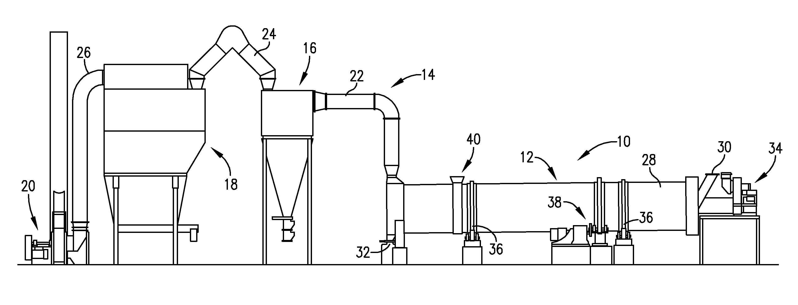
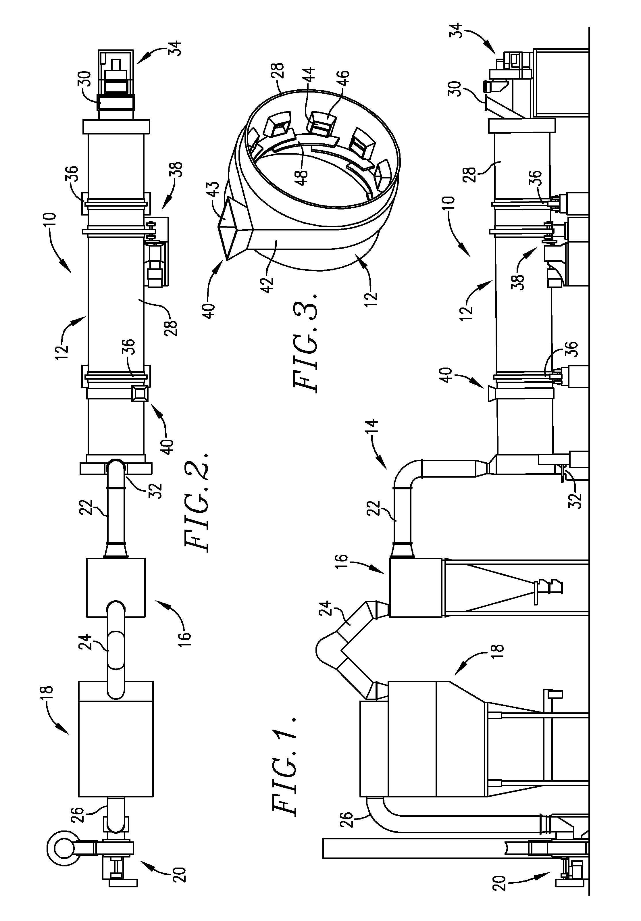
[0020]Turning now to FIGS. 1 and 2, a wet fracturing sand drying plant assembly 10 is illustrated, which broadly includes an induced-draft, single-pass, co-current rotary dryer 12, and a particulate removal system 14 including a knock-out box 16 and baghouse filter 18. An induced-draft dryer fan 20 is situated upstream of the system 14 and dryer 12, as shown. Appropriate ducts 22, 24, and 26 operably interconnect the dryer 12, knock-out 16, baghouse filter 18, and fan 20. The components of the particulate removal system are conventional, and therefore need not be described in detail.

[0021]The dryer 12 includes an elongated tubular shell 28 having a wet sand inlet 30 and a dry sand outlet 32, located at the opposite extreme ends of the shell 28. A burner / blower 34 is located at the inlet end of shell 28 and is operable to heat the air passing in a co-current fashion through the shell 28. The shell 28 is oriented at a small downward angle, such that the inlet end thereof is above the ...


PUM

PropertyMeasurementUnit
diameteraaaaaaaaaa
temperatureaaaaaaaaaa
lengthaaaaaaaaaa

Abstract

An improved, energy efficient method and apparatus for conditioning of fracturing sand provides an elongated, rotatable drying / cooling shell with co-current flow of heated air and sand through the shell. Structure operable to deliver additional quantities of wet sand into the shell is provided at a zone between the shell inlet and outlet, and downstream of the point where the initial quantity of wet sand is substantially dry. The additional quantities of wet sand mix with the initial quantities of substantially dry sand in order to evaporatively dry the additional quantity of wet sand, and to cool the initial and additional quantities of wet sand.

Description

CROSS-REFERENCE TO RELATED APPLICATION[0001]This application claims the benefit of US Provisional Application Ser. No. 61 / 879,345, filed Sep. 18, 2013, which is incorporated by reference herein in its entirety.BACKGROUND OF THE INVENTION[0002]1. Field of the Invention[0003]The present invention is broadly concerned with improved methods and apparatus for the drying / cooling of fracturing sands used in petroleum rock formations. More particularly, the invention is concerned with such methods and apparatus wherein use is made of an induced-draft, co-current, single-pass rotary dryer equipped with an additional wet sand input device situated between the primary wet sand inlet at one end of the dryer, and a dried sand outlet at the other end thereof. The additional wet sand added to the dryer serves to cool the initially introduced dried sand while simultaneously drying the additional wet sand by evaporation. The final conditioned product from the rotary dryer has suitable moisture and t...

Claims


Application Information

Patent Timeline
Patent Type & Authority Patents(United States)
IPC IPC(8): F26B9/04F26B21/00F26B25/16F26B23/00
CPCF26B21/004F26B25/16F26B23/00F26B5/16F26B2200/14F26B11/04F26B25/002
Inventor SHINN, DONALD E.
Owner INDAL ACCESSORIES
Why Eureka
Try Eureka