
Spectral stitching method to increase instantaneous bandwidth in vector signal analyzers

a vector signal analyzer and instantaneous bandwidth technology, applied in the field of signal processing, can solve the problems of inability to achieve the largest possible bandwidth, inability to achieve more than 8 bits of dynamic range without dsp correction, and inability to achieve the maximum bandwidth

Active Publication Date: 2016-04-26
NATIONAL INSTRUMENTS
View PDF7 Cites 9 Cited by
  • Summary
  • Abstract
  • Description
  • Claims
  • Application Information

AI Technical Summary

Benefits of technology

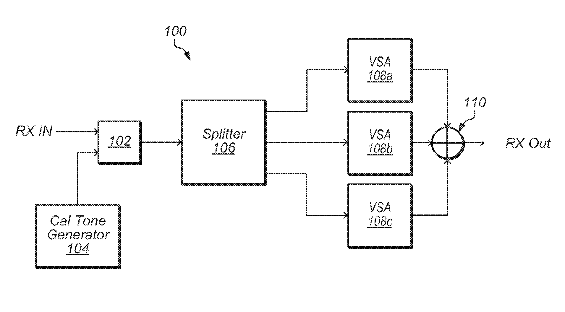
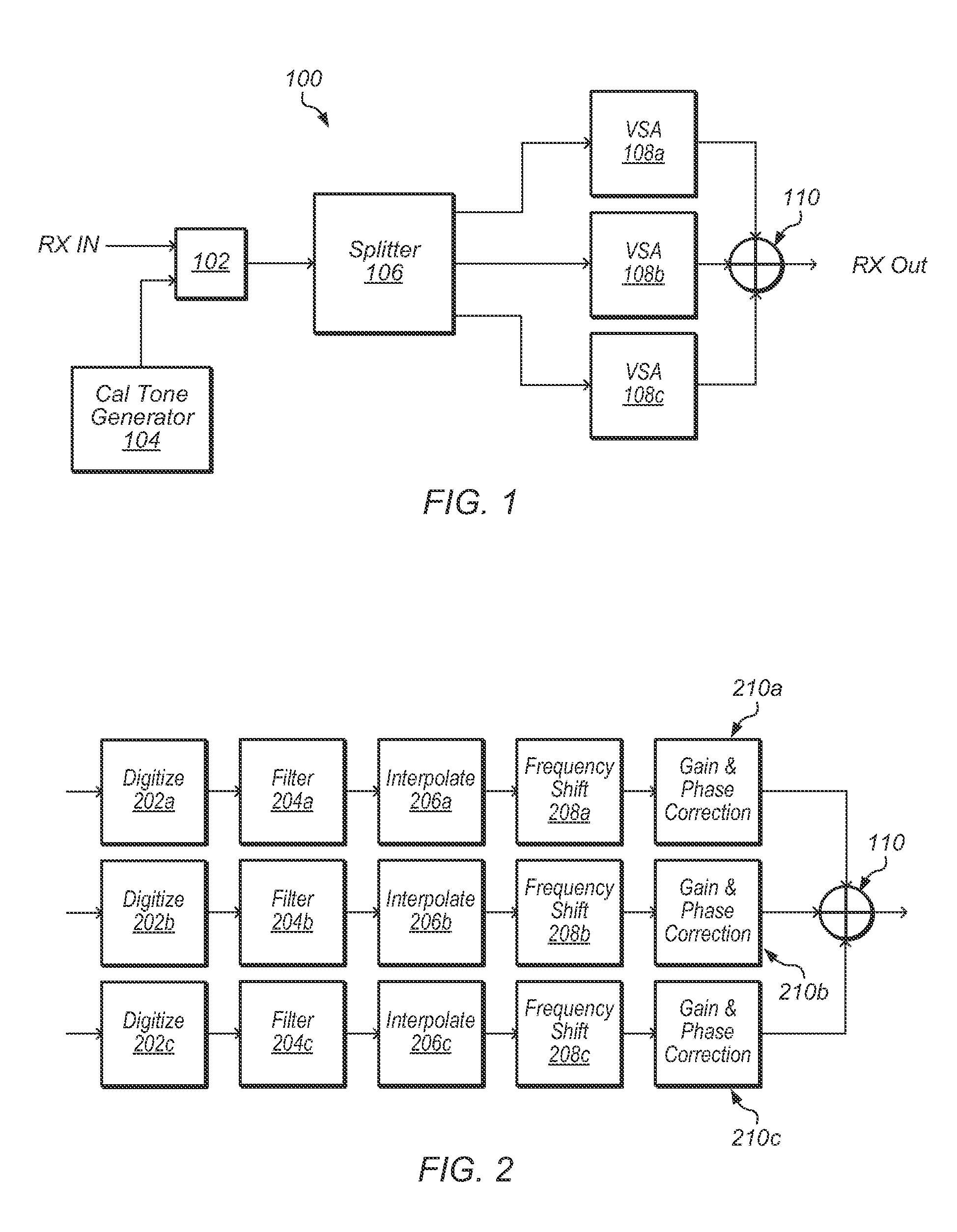
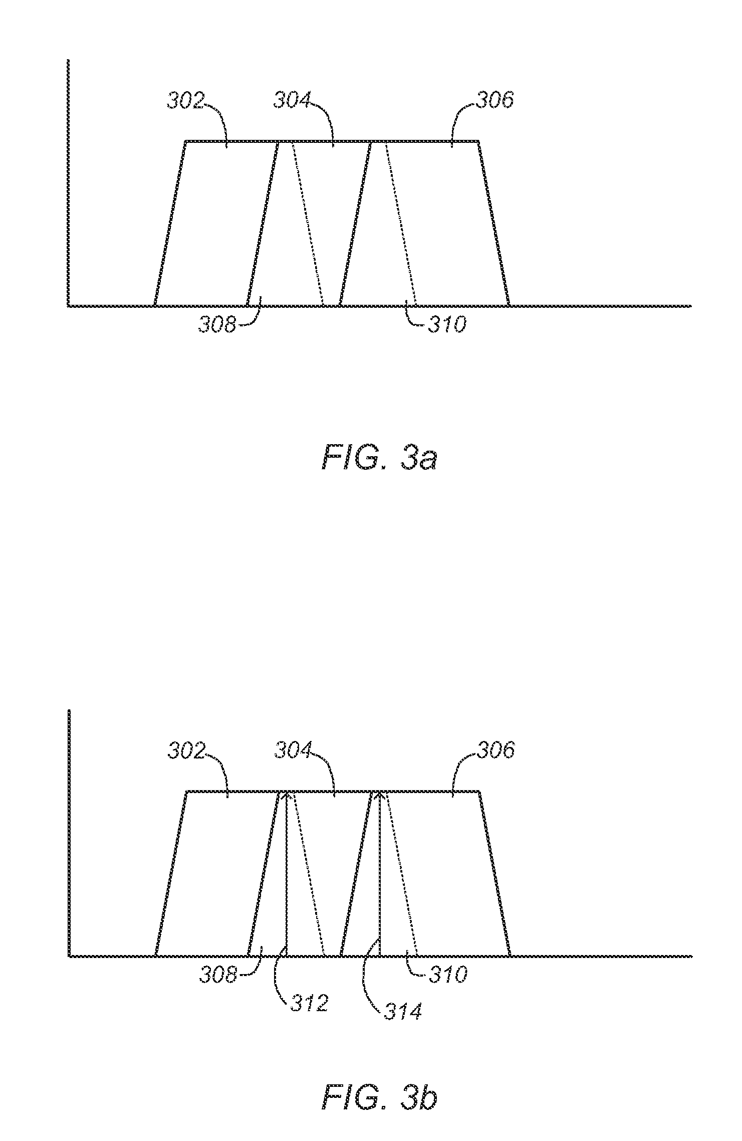
The patent describes a method and system for processing signals using multiple vector signal analyzers (VSAs). These VSAs analyze different frequency bands of an input signal and combine them to create an aggregate frequency band with a continuous frequency response over a wider range of frequencies. The VSAs are synchronized with each other and can adjust the gain and phase of the signals they receive. The system can also include a signal splitter and multiple parallel signal processing pathways to further enhance the signal processing capabilities. The technical effects of this invention include improved signal quality, reduced interference, and improved synchronization between VSAs.

Problems solved by technology

In many cases, the limiting factor in achieving the largest possible bandwidth is the sample rate of the analog-to-digital converters (ADCs) and digital-to-analog converters (DACs).
This method introduces errors resulting from inaccuracies in staggering the time alignment and from differences in the magnitude and phase between the various ADCs.
In general, it is difficult to achieve more than 8 bits of dynamic range without DSP correction.
Online methods typically have to assume something about the input signal, and other negative effects occur when those assumptions are broken.
However, this method typically creates a DC leakage spur and an image spur.
In addition, the method only scales to two converts.

Method used


Image

  • Spectral stitching method to increase instantaneous bandwidth in vector signal analyzers
  • Spectral stitching method to increase instantaneous bandwidth in vector signal analyzers
  • Spectral stitching method to increase instantaneous bandwidth in vector signal analyzers

Examples


Embodiment Construction

Incorporation by Reference

[0026]The following references are incorporated by reference as if fully and completely disclosed herein:

[0027]U.S. Patent Application No. 2013 / 0343490, filed Jun. 20, 2012, entitled “Synchronizing Receivers in a Signal Acquisition System”, invented by Wertz et al.;

[0028]U.S. Pat. No. 7,624,294, issued on Nov. 24, 2009, entitled “Synchronizing Measurement Devices Using Trigger Signals”, invented by Craig M. Conway; and

[0029]U.S. Pat. No. 7,315,791, issued on Jan. 1, 2008, entitled “Application Programming Interface for Synchronizing Multiple Instrumentation Devices”, invented by Kosta Ilic et al.

TERMINOLOGY

[0030]The following is a glossary of terms used in the present application:

[0031]Memory Medium—Any of various types of memory devices or storage devices. The term “memory medium” is intended to include an installation medium, e.g., a CD-ROM, floppy disks 105, or tape device; a computer system memory or random access memory such as DRAM, DDR RAM, SRAM, EDO...


PUM


Abstract

Various embodiments are described of devices and associated methods for processing a signal using a plurality of vector signal analyzers (VSAs). An input signal may be split and provided to a plurality of VSAs, each of which may process a respective frequency band of the signal, where the respective frequency bands have regions of overlap. Each VSA may adjust the gain and phase of its respective signal such that continuity of phase and magnitude is preserved through the regions of overlap. The correction of gain and phase may be accomplished by a complex multiply with a complex calibration constant. A complex calibration constant may be determined for each VSA by comparing the gain and phase of one or more calibration tones generated with each region of overlap, as measured by each of the VSAs.

Description

FIELD OF THE INVENTION[0001]The present invention relates to the field of signal processing, and more particularly to systems and methods for increasing instantaneous bandwidth in a vector signal analyzer or a vector signal generator.DESCRIPTION OF THE RELATED ART[0002]Instantaneous bandwidth is an important banner specification for all radio frequency (RF) vector signal analyzers (VSAs) and RF vector signal generators (VSGs). The desire of the industry is to increase the bandwidth as much as possible without sacrificing dynamic range. In many cases, the limiting factor in achieving the largest possible bandwidth is the sample rate of the analog-to-digital converters (ADCs) and digital-to-analog converters (DACs). While ADC and DAC vendors are always working to increase the converter rates, there still exists a desire in many applications for bandwidths that exceed the capabilities of state-of-the-art ADCs and DACs. There are several different methods within the industry for achievi...

Claims


Application Information

Patent Timeline
Patent Type & Authority Patents(United States)
IPC IPC(8): H04B17/309H04W24/08H04B17/00H04B1/12
CPCH04B17/309H04W24/08H04B17/00H04B1/12H04B17/0085H04B17/21H04W56/003H04L7/0087H04L27/3827H04W72/044
Inventor DARK, STEPHEN L.BAKER, DANIEL J.AMMERMAN, JOHNATHAN R.W.
Owner NATIONAL INSTRUMENTS
Learn More