Laryngoscope

a technology of laryngoscope and otoscope, which is applied in the field of laryngoscope, can solve the problems of increasing the cost of the equipment required to perform efficiently, increasing the cost of the viewing device, and the patient's intubation difficulty, and achieves the effects of less prone to contamination, and less robustness

Active Publication Date: 2016-05-10
INDIAN OCEAN MEDICAL INC
View PDF64 Cites 8 Cited by
  • Summary
  • Abstract
  • Description
  • Claims
  • Application Information

AI Technical Summary

Benefits of technology

[0009]The blade may comprise a sleeve portion that completely or partially surrounds the blade holding element and a distal extension which is prefera...

Problems solved by technology

However, some patients are known to be difficult to intubate, especially if there are anatomical abnormalities (e.g. if the larynx lies particularly anteriorly) or if there are injuries.
He or she would then need a second video laryngoscope with ...

Method used


Image

  • Laryngoscope
  • Laryngoscope
  • Laryngoscope

Examples


embodiment 1

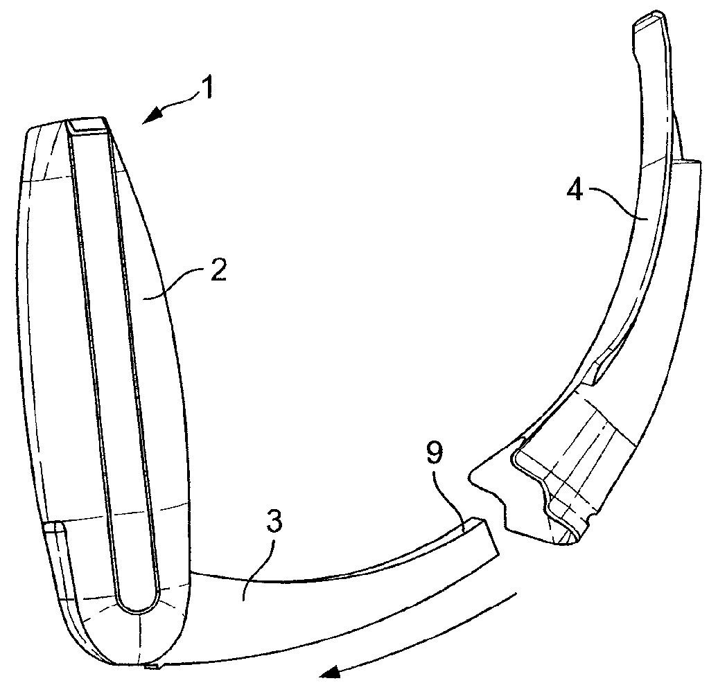
[0075]FIG. 3 shows part of a laryngoscope according to a first embodiment of the invention, in which the outer contour of the blade holding element (3) corresponds substantially to the inner shape of the sleeves (5a, 5b) of the standard and difficult blades (4a, 4b) so that the blades can be used interchangeably with the same laryngoscope. The fixed camera element (9) is located at the distal end of the blade holding element (3).

[0076]In FIGS. 4a and 5a, the blade holding element (3) is fitted with a short standard curved blade and with a long standard curved blade (4a), respectively. Line H-H passes between the centre of the lens of the camera (9) and the pivotal joint between the handle (2) and the blade holding element (3). The camera (9) is arranged so that the centre of the visual field captured by the camera is located at an angle α1 ranging for example from 5° to 15° from line H-H in the plan defined by line H-H and the longitudinal axis of the handle (2). In FIGS. 4a and 5a,...

embodiment 2

[0080]FIG. 7 shows part of a laryngoscope according to a second embodiment of the invention. The main difference with the laryngoscope of FIG. 3 lies in the position of the camera (9). The camera (9) is arranged so that the centre of the visual field captured by the camera is located at an angle α2 ranging for example from 15° to 25° from line H-H in the plan defined by line H-H and the longitudinal axis of the handle (2). The angle α2 is greater than α1 (for example 17°)

[0081]In FIGS. 8a and 9a, the blade holding element (3) is fitted with a short standard curved blade and with a long standard curved blade (4a), respectively. The views captured by the camera (9) are shown in FIGS. 8b and 9b and include the tip of the extension (7a). The views are clear and not distorted (as illustrated by the perfectly square grid). These are satisfactory views that, when positioned in the patient, precisely focus on the laryngeal inlet of the patient.

[0082]In FIG. 10a, the blade holding element (3...

embodiment 3

[0083]FIG. 11 shows part of a laryngoscope according to a third embodiment of the invention. The camera (9) is arranged so that the centre of the visual field captured by the camera is located at an angle α3 ranging for example from 25° to 40° from line H-H in the plan defined by line H-H and the longitudinal axis of the handle (2). The angle α3 is greater than α1 and α2 (for example 32°).

[0084]In FIGS. 12a and 13a, the blade holding element (3) is fitted with a short standard curved blade and with a long standard curved blade (4a), respectively. In addition, a wedge prism is fitted at the distal end of the sleeve (6a) to direct the viewing field towards the tip of the extension (7a).

[0085]FIGS. 12b and 13b show the views obtained using the blades of FIGS. 12a and 13a and the re-positioning of the camera on its own (i.e. without a wedge prism). No distortion is observed and the view is clear. However, the extension (7a) intrudes into (approximately ⅓ of) the viewing field.

[0086]By c...


PUM


Abstract

A laryngoscope comprising a handle, a blade holding element, a detachable blade, means for viewing the laryngeal inlet of a patient and means for adjusting the viewing field. The means for adjusting the viewing field may comprise a light refracting means. Alternatively, in embodiments in which the viewing means comprises at least two fixed cameras elements directed to at least two different viewing fields, the means for adjusting the viewing field may comprise means for switching from one camera to the other or, in embodiments in which the viewing means comprises a movable camera element, the means for adjusting the viewing field may comprise mechanical or electronic means for controlling the movement of the camera. A method for viewing the laryngeal inlet of a patient using a laryngoscope comprising the step of adjusting the viewing field is also covered.

Description

FIELD OF THE INVENTION[0001]This application relates to a laryngoscope and more particularly to a video laryngoscope.BACKGROUND OF THE INVENTION[0002]Whereas a conventional laryngoscope is used by a physician to visualise the path to the trachea by manipulating the patient's anatomy to establish a direct line of sight, a video laryngoscope provides a view of the glottis and trachea without the need for such manipulation, which is clearly advantageous.[0003]In recent times video laryngoscopes have also been provided that have removable, disposable blades, to remove the need for sterilisation.[0004]A laryngoscope is a device which is used by clinicians during tracheal intubation and that assists with intubation by allowing the clinician to visualise the path of the endotracheal tube as it passes through the glottis towards the trachea. In its most recent form a laryngoscope comprises a handle and a blade and often includes a light source. Some laryngoscopes are also provided with view...

Claims


Application Information

Patent Timeline
IPC IPC(8): A61B1/32A61B1/05A61B1/00A61B1/045A61B1/267
CPCA61B1/05A61B1/00096A61B1/00183A61B1/045A61B1/267
Inventor PATEL, ANILYOUNG, PETERPLEVNIK, MARKO
Owner INDIAN OCEAN MEDICAL INC
Why Eureka
Try Eureka