Systems for and methods of fusing a sacroiliac joint

a technology of sacroiliac joint and system, which is applied in the field of medical devices and methods, can solve the problems of increased operative time, increased hospitalization, pain and recovery time, and substantial problems with respect to the fixation and fusion of the sacroiliac join

Active Publication Date: 2016-05-10
JCBD
View PDF460 Cites 9 Cited by
  • Summary
  • Abstract
  • Description
  • Claims
  • Application Information

AI Technical Summary

Benefits of technology

[0021]Yet another implementation of the present disclosure may take the form of a medical kit for the fusion of a sacroiliac joint including a caudal access region and a joint plane. In one embodiment, the kit includes: a) a delivery tool comprising an implant arm and an anchor arm coupled to the implant arm; b) a joint implant comprising a bore defined therein that extends generally transverse to a longitudinal length of the joint implant; and c) an anchor element configured to be received in the bore of the joint implant. The bore of the implant, the implant, the implant arm and the anchor arm have an as-manufactured configuration that allows the anchor arm to properly align the anchor element to be received in the bore of the implant when the implant is coupled to the implant arm.

Problems solved by technology

However, while each of these methods has been utilized for fixation and fusion of the sacroiliac joint over the past several decades, substantial problems with respect to the fixation and fusion of the sacroiliac joint remain unresolved.
A significant problem with certain conventional methods for fixation and fusion of the sacroiliac joint including the anterior approach, posterior approach, or lateral approach may be that the surgeon has to make a substantial incision in the skin and tissues for direct access to the sacroiliac joint involved.
Often referred to as an “open surgery”, these procedures have the attendant disadvantages of requiring general anesthesia and can involve increased operative time, hospitalization, pain, and recovery time due to the extensive soft tissue damage resulting from the open surgery.
A danger to open surgery using the anterior approach can be damage to the L5 nerve root, which lies approximately two centimeters medial to the sacroiliac joint or damage to the major blood vessels.
Use of trans-sacroiliac and S1 pedicle-iliac bone implants can also involve the risk of damage to the lumbosacral neurovascular elements.
Damage to the lumbosacral neurovascular elements as well as delayed union or non-union of the sacroiliac joint by use of these procedures may require revision surgery to remove all or a portion of the implants or repeat surgery as to these complications.
Another significant problem with conventional procedures utilizing minimally invasive small opening procedures can be that the procedures are technically difficult, requiring biplanar fluoroscopy of the articular surfaces of the sacroiliac joint and extensive surgical training and experience.
Despite the level of surgical training and experience, there is a substantial incidence of damage to the lumbosacral neurovascular elements.
Additionally, sacral anomalies can further lead to mal-placement of implants leading to damage of surrounding structures.
Additionally, these procedures are often performed without fusion of the sacroiliac joint, which does not remove the degenerative joint surface and thereby does not address the degenerative condition of the sacroiliac joint, which may lead to continued or recurrent sacroiliac joint pain.
Another significant problem with conventional procedures can be the utilization of multiple trans-sacroiliac elongate implants, which do not include a threaded surface.
This approach requires the creation of trans-sacroiliac bores in the pelvis and nearby sacral foramen, which can be of relatively large dimension and which are subsequently broached with instruments, which can result in bone being impacted into the pelvis and neuroforamen.
The creation of the trans-sacroiliac bores and subsequent broaching of the bores requires a guide pin, which may be inadvertently advanced into the pelvis or sacral foramen, resulting in damage to other structures.
Additionally, producing the trans-sacroiliac bores, broaching, or placement of the elongate implants may result in damage to the lumbosacral neurovascular elements, as above discussed.
Additionally, there may be no actual fusion of the articular portion of the sacroiliac joint, which may result in continued or recurrent pain requiring additional surgery.
Another substantial problem with conventional procedures can be that placement of posterior extra-articular distracting fusion implants and bone grafts may be inadequate with respect to removal of the articular surface or preparation of cortical bone, the implant structure and fixation of the sacroiliac joint.
The conventional procedures may not remove sufficient amounts of the articular surfaces or cortical surfaces of the sacroiliac joint to relieve pain in the sacroiliac joint.
The conventional implant structures may have insufficient or avoid engagement with the articular surfaces or cortical bone of the sacroiliac joint for adequate fixation or fusion.
The failure to sufficiently stabilize and fuse the sacroiliac joint with the conventional implant structures and methods may result in a failure to relieve the condition of sacroiliac joint being treated.
Additionally, conventional methods of driving apart a sacrum and ilium may lead to mal-alignment of the sacroiliac joint and increased pain.

Method used


Image

  • Systems for and methods of fusing a sacroiliac joint
  • Systems for and methods of fusing a sacroiliac joint
  • Systems for and methods of fusing a sacroiliac joint

Examples


first embodiment

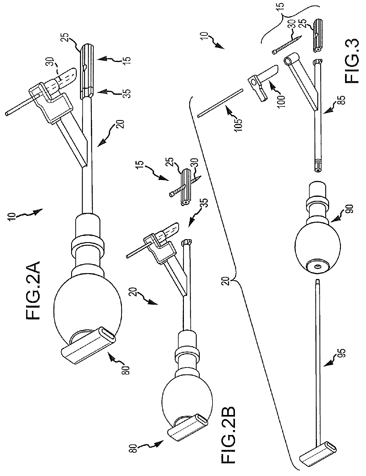
[0197]To begin a detailed discussion of the system 10, reference is made to FIGS. 2A-3. FIG. 2A is an isometric view of the system 10. FIG. 2B is the same view as FIG. 2A, except an implant assembly 15 of the system 10 is separated from a delivery tool 20 of the system 10. FIG. 3 is the same view as FIG. 2A, except the system 10 is shown exploded to better illustrate the components of the system 10.

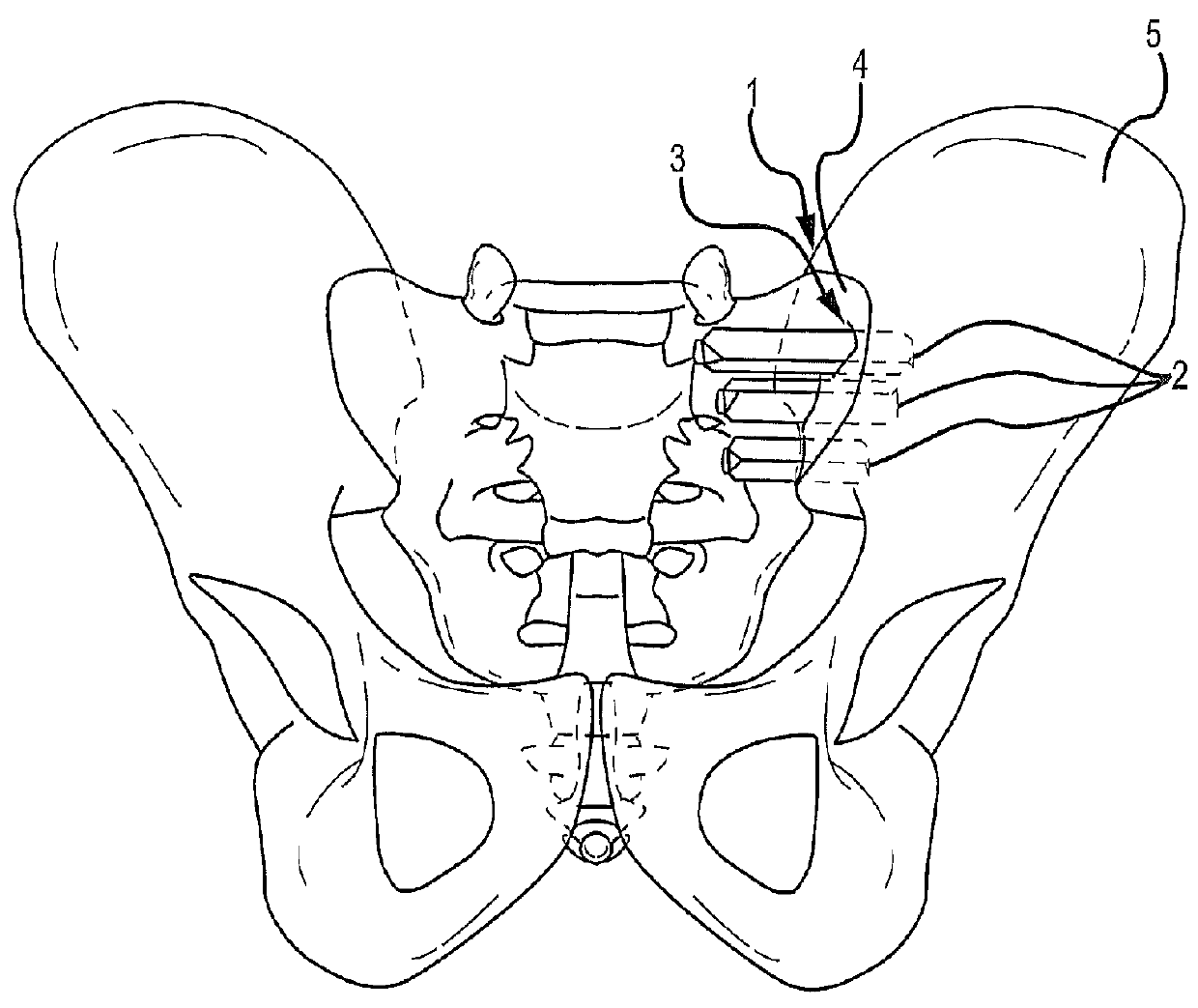
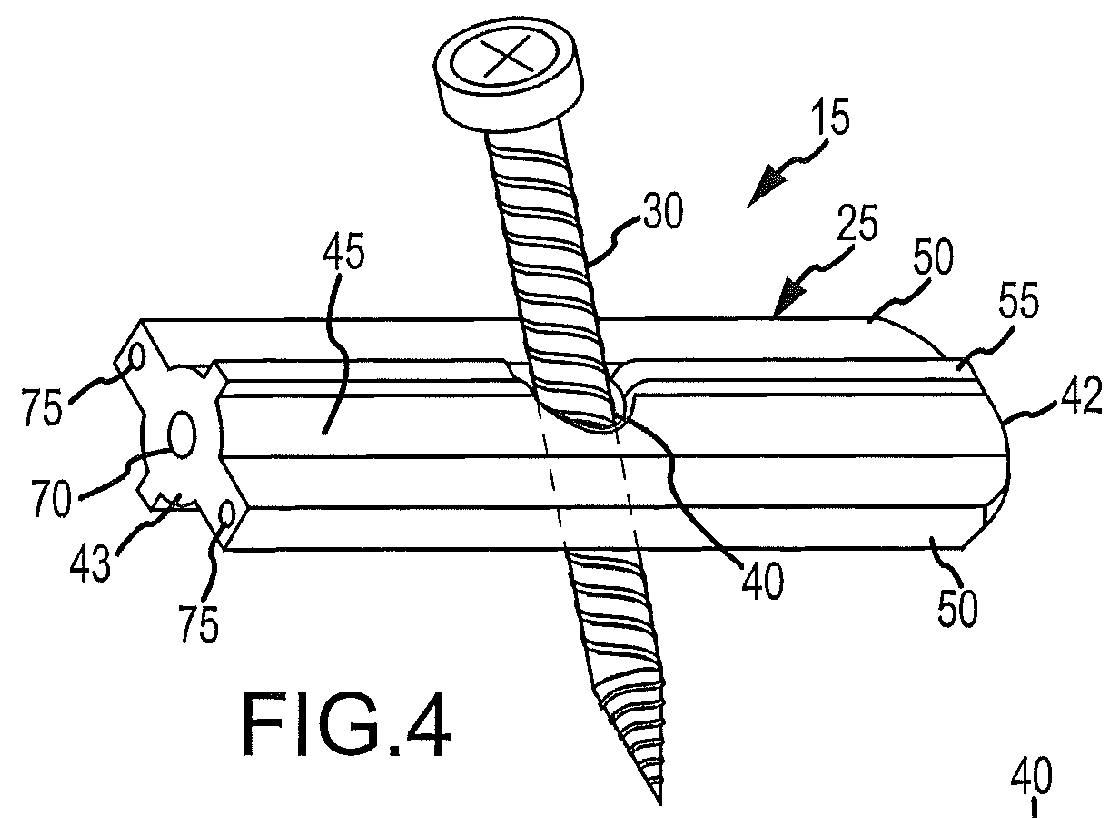
[0198]As can be understood from FIGS. 2A and 2B, the system 10 includes a delivery tool 20 and an implant assembly 15 for implanting at the sacroiliac joint via the delivery tool 20, the implant assembly 15 being for fusing the sacroiliac joint. As indicated in FIG. 3, the implant assembly 15 includes an implant 25 and an anchor element 30 (e.g., a bone screw or other elongated body). As discussed below in greater detail, during the implantation of the implant assembly 15 at the sacroiliac joint, the implant 25 and anchor element 30 are supported by a distal end 35 of the delivery tool 20...

second embodiment

[0257]To begin a detailed discussion of the system 10, reference is made to FIGS. 32-33. FIG. 32 is an isometric view of the system 10, and FIG. 33 is the same view as FIG. 32, except the system 10 is shown exploded to better illustrate the components of the system 10.

[0258]As can be understood from FIGS. 32 and 33, the system 10 includes a delivery tool 20 and an implant assembly 15 for implanting at the sacroiliac joint via the delivery tool 20, the implant assembly 15 being for fusing the sacroiliac joint. As indicated in FIG. 33, the implant assembly 15 includes an implant 25 and an anchor element 30 (e.g., a bone screw or other elongated body). In one embodiment, the implant assembly 15 is the same as that described above with respect to FIGS. 4-17. As discussed below in greater detail, during the implantation of the implant assembly 15 at the sacroiliac joint, the implant 25 and anchor element 30 are supported by a distal end 35 of the delivery tool 20, as illustrated in FIG. ...

third embodiment

[0272]To begin a detailed discussion of the system 10, reference is made to FIGS. 37-40. FIGS. 37 and 38 are different isometric views of the system 10. FIG. 39 is the same view as FIG. 37, except the system 10 is shown exploded to better illustrate the components of the system 10. FIG. 40 is a side elevation of the system wherein the tool is attached to the implant assembly for delivery of the implant assembly to the sacroiliac joint.

[0273]As can be understood from FIGS. 37-40, the system 10 includes a delivery tool 20 and an implant assembly 15 for implanting at the sacroiliac joint via the delivery tool 20, the implant assembly 15 being for fusing the sacroiliac joint. As indicated in FIG. 39, the implant assembly 15 includes an implant 25 and an anchor element 30 (e.g., a bone screw or other elongated body).

[0274]As can be understood from a comparison of FIGS. 2A-3 to FIGS. 37-40, the delivery tool 20 of FIGS. 2A-3 is the same as the delivery tool 20 of FIGS. 37-40. Thus, for a ...


PUM


Abstract

Systems for and methods of fusing a sacroiliac joint are provided which include an implant assembly adapted to be inserted into the joint space defined by the bones of a sacrum and an ilium, a delivery tool and means for inserting the implant assembly into the joint. The implant assembly includes a body disposed intermediate distal and proximate end portions thereof and having oppositely disposed side members adapted to expandably engage the sacroiliac joint following insertion of the assembly into the joint space. A tool is provided and provides a means for placing the implant assembly adjacent the sacroiliac joint, inserting it into the joint space and expanding means are thereafter applied to expand the oppositely disposed side members into operative engagement with the joint.

Description

CROSS REFERENCE TO RELATED APPLICATIONS[0001]The present application claims priority to and incorporates by reference in its entirety U.S. Provisional Patent Application No. 61 / 674,277, filed Jul. 20, 2012 and No. 61 / 800,120, filed Mar. 15, 2013.[0002]The present application is a continuation-in-part (CIP) application of U.S. patent application Ser. No. 13 / 475,695 (“the '695 application”), which was filed May 18, 2012. The '695 application is a continuation-in-part (CIP) application of U.S. patent application Ser. No. 12 / 998,712 (“the '712 application”), which was filed May 23, 2011. The '712 application is the National Stage of International Patent Cooperation Treaty Patent Application PCT / US2011 / 000070 (the “PCT application”), which was filed Jan. 13, 2011. The PCT application claims priority to U.S. Provisional Patent Application 61 / 335,947, which was filed Jan. 13, 2010.[0003]The present application is also a continuation-in-part of and claims priority to U.S. patent application...

Claims


Application Information

Patent Timeline
Patent Type & Authority Patents(United States)
IPC IPC(8): A61F2/44A61F2/30A61B17/16A61B17/17A61F2/46A61B17/02A61B17/00A61B17/86A61B17/70
CPCA61F2/4455A61B17/1626A61B17/1739A61B17/1757A61B17/7055A61B17/7074A61F2/30988A61F2/4611A61B17/025A61B17/7043A61B17/8645A61B2017/0046A61F2002/304A61F2002/30163A61F2002/30382A61F2002/30401A61F2002/30428A61F2002/30484A61F2002/30504A61F2002/30509A61F2002/30579A61F2002/30601A61F2002/30622A61F2002/30774A61F2002/30828A61F2002/30995A61F2002/4687A61F2310/00017A61F2310/00023A61F2310/00179A61F2310/00359A61B17/1671A61B2017/00876A61F2/4405A61F2/4603A61F2002/30179A61F2002/30331A61F2002/305A61F2002/30507B33Y80/00A61F2002/3055
Inventor DONNER, EDWARD JEFFREYDONNER, CHRISTOPHER THOMAS
Owner JCBD
Why Eureka
Try Eureka