

Position detection device
a technology of position detection and detection device, which is applied in the direction of semiconductor devices, instruments, computing, etc., can solve the problems of limited use, inability to maintain and manage, and inevitable exchange of batteries
- Summary
- Abstract
- Description
- Claims
- Application Information
AI Technical Summary
Benefits of technology
Problems solved by technology
Method used
Image

Examples
first embodiment
Principle
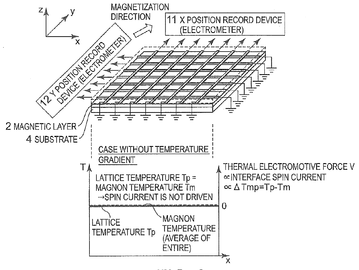
[0045]First, the basic structure and principle of the spin Seebeck effect described in Patent Literature 1 are illustrated in FIG. 25. A basic element structure includes a magnetic layer having magnetization formed on a substrate and electrodes disposed on the ends of the magnetic layer. When a temperature gradient in an in-plane direction is applied to this structure, a spin current is induced at an interface between the electrode and the magnetic layer. This spin current is converted into an electric current (electromotive force) by an inverse spin Hall effect in the electrode, and “thermoelectric conversion in which a thermal electromotive force is generated from a temperature difference” becomes possible.
[0046]In the microscopic spin Seebeck effect theory described in Non Patent Literature 1 (Physical Review B 81, 214418), it can be understood that this spin current is driven by a temperature difference between “lattice temperature Tp” and “magnon temperature Tm”. Here,...
example 1
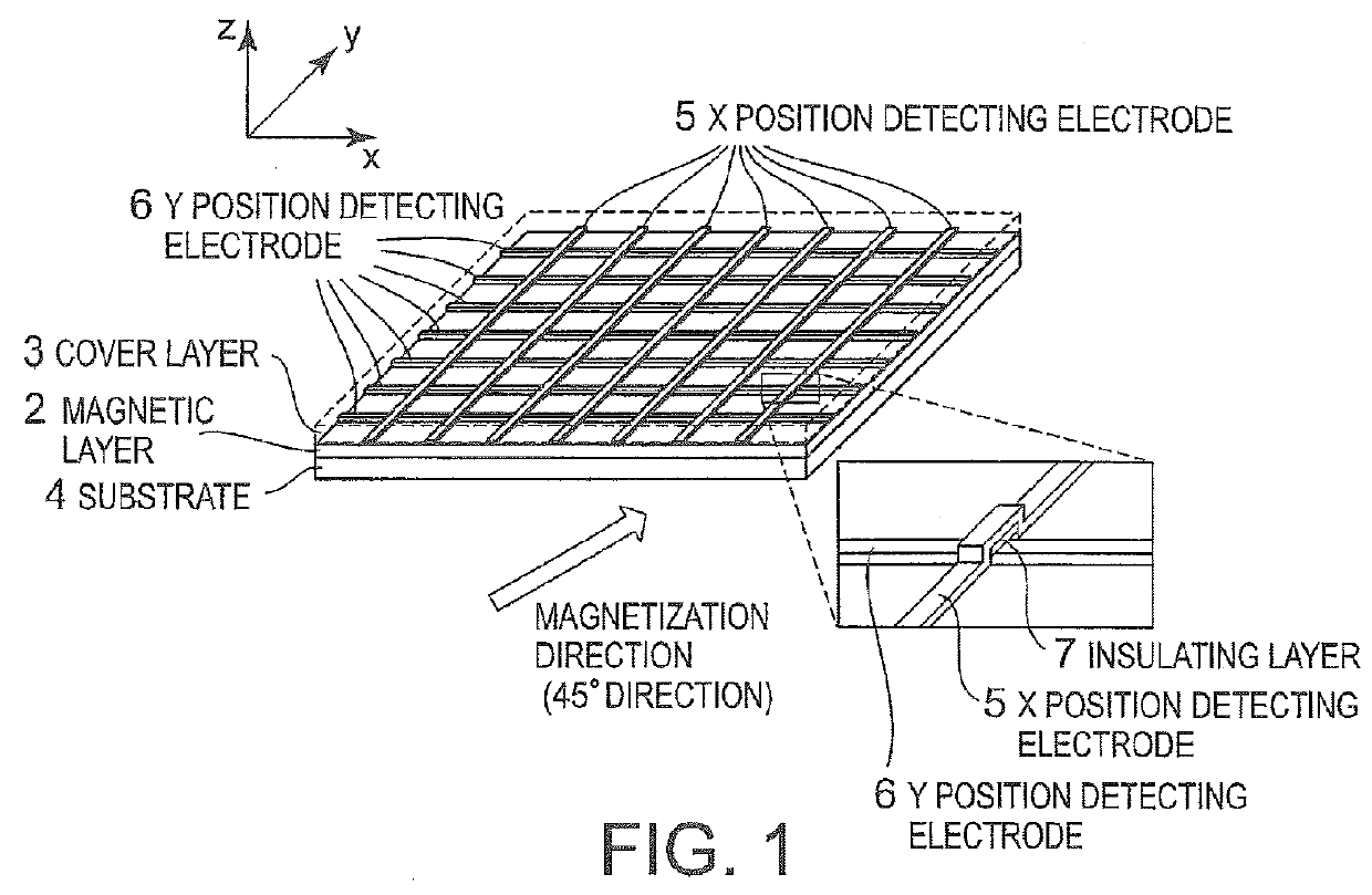
[0076]FIG. 7 illustrates a specific example of this invention.
[0077]In this example, as the magnetic layer 2, an yttrium iron garnet film is used, in which a part of Y-site is replaced with Bi (hereinafter referred to as Bi:YIG film, in a composition of BiY2Fe5O12). Pt is used for the X position detecting electrode 5 and the Y position detecting electrode 6. Here, the Bi:YIG film has a thickness of 5 μm, and the Pt electrode has a thickness of 20 nm. In addition, each Pt electrode has a line shape having a line width of 100 μm, and an interval between the electrodes is 1 mm.
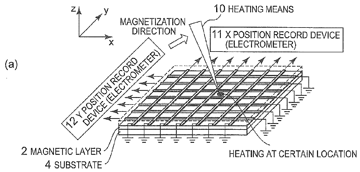
[0078]A quartz glass substrate having a thickness of 300 μm is used as the substrate 4, and an acrylic resin having a thickness of 50 μm is used as the cover layer 3. A polyimide resin is used as the insulating layer 7. As the heating means 10 as a separate body from the thermoelectric conversion portion, a pen having the tip heated at 40° C. is used.
[0079]The magnetic layer 2 made of Bi:YIG is formed by an aeros...
fifth embodiments
Second to Fifth Embodiments
[0082]In the first embodiment, as the position information input means for inputting position information, the heating means 10 is used, which heats an arbitrary location on the plane of the thermoelectric conversion portion separately from the position detection element (thermoelectric conversion portion). However, this invention is not limited to this systematic device. In other words, according to this invention, when the energy form interface means for heating an arbitrary location on the plane when receiving an external trigger in various energy forms is provided (embedded) as the position information input means integrally with the position detection element (thermoelectric conversion portion), the input of position information can be realized by the external trigger in various energy forms.
[0083]Actually, heat is the most general energy form, and various kinds of energy such as an electromagnetic wave and vibration finally become heat in many cases....
PUM
 Abstract
Description
Claims
Application Information