Wideband voltage-driven electrically-small loop antenna system and related method

a voltage-driven, electrically-small-loop antenna technology, applied in the direction of rf amplifiers, multi-port networks, transmission, etc., can solve the problems of low efficiency of these schemes, further degrading system efficiency, and low loss,

Active Publication Date: 2016-05-24
ROCKWELL COLLINS INC
View PDF6 Cites 6 Cited by
  • Summary
  • Abstract
  • Description
  • Claims
  • Application Information

AI Technical Summary

Problems solved by technology

While an improvement over traditional use of Class-AB PA to perform this task, the efficiency of these schemes may be quite low, not exceeding the ratio of the radiation resistance of the loop to twice the resistance (Rds) on of the switching devices.
The switching losses of this scheme are expected to further degrade system efficiency.
However, the concept requires low-loss, fast switching RF power devices, to take full advantage of the approach.
The losses resulting from finite switching device ON resistance attempting to supply power into vanishingly small loop radiation resistances, combined with the Digital Signal Processor (DSP) power needed to generate the RF-PWM signals severely limit the efficiency of the concept.
In addition, the power required to overcome the inductive reactance of the loop feed point and sufficiently resonate the loop may require multiple power amplifiers to create sufficient power into the loop antenna to force radiation.
This technique, while applicable for cancellation of signal harmonics, requires a complicated power amplifier configuration.
However, a loop antenna, as described by the previous references, when driven by a voltage source at a feed point along its circumference will possess a non-uniform directional radiation pattern over frequency, affecting the ability to cancel harmonic radiation from the harmonically-rich switched voltage source.
These attempts fail to address that effectiveness of the loop antenna increases with frequency up to the resonant frequency of the loop or a harmonic of the resonant frequency of the loop.
Therefore, such a system may not meet a nominal harmonic radiation specification (e.g. −80 dBc).

Method used


Image

  • Wideband voltage-driven electrically-small loop antenna system and related method
  • Wideband voltage-driven electrically-small loop antenna system and related method
  • Wideband voltage-driven electrically-small loop antenna system and related method

Examples


Embodiment Construction

[0029]Reference will now be made in detail to the presently preferred embodiments of the invention, examples of which are illustrated in the accompanying drawings.

[0030]The following description presents certain specific embodiments of the present invention. However, the present invention may be embodied in a multitude of different ways as defined and covered by the claims. In this description, reference is made to the drawings wherein like parts are designated with like numerals throughout.

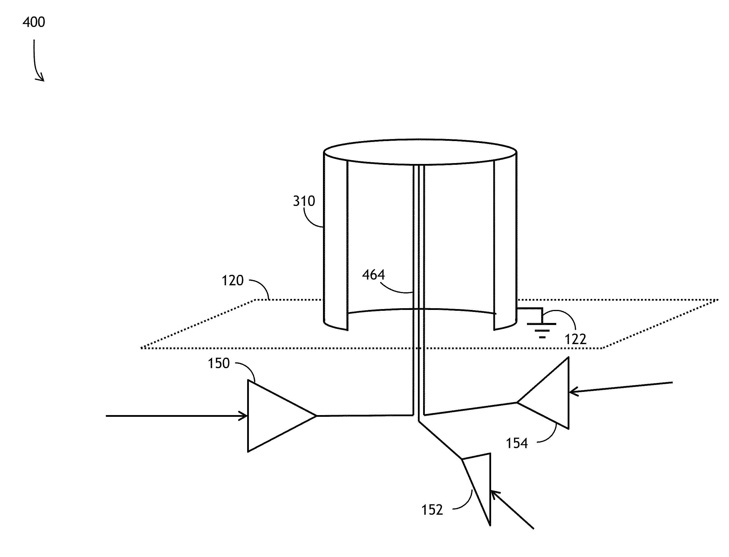
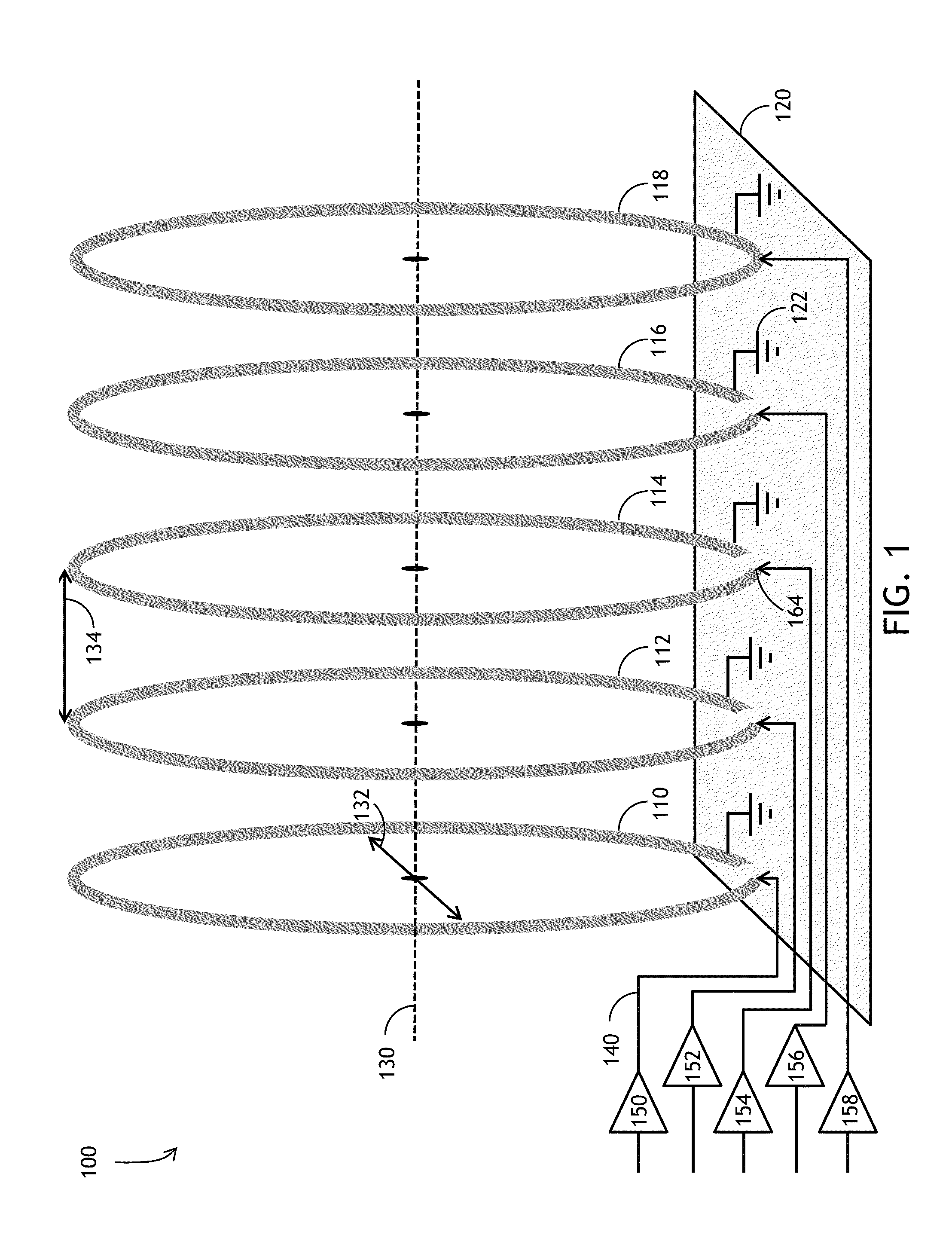
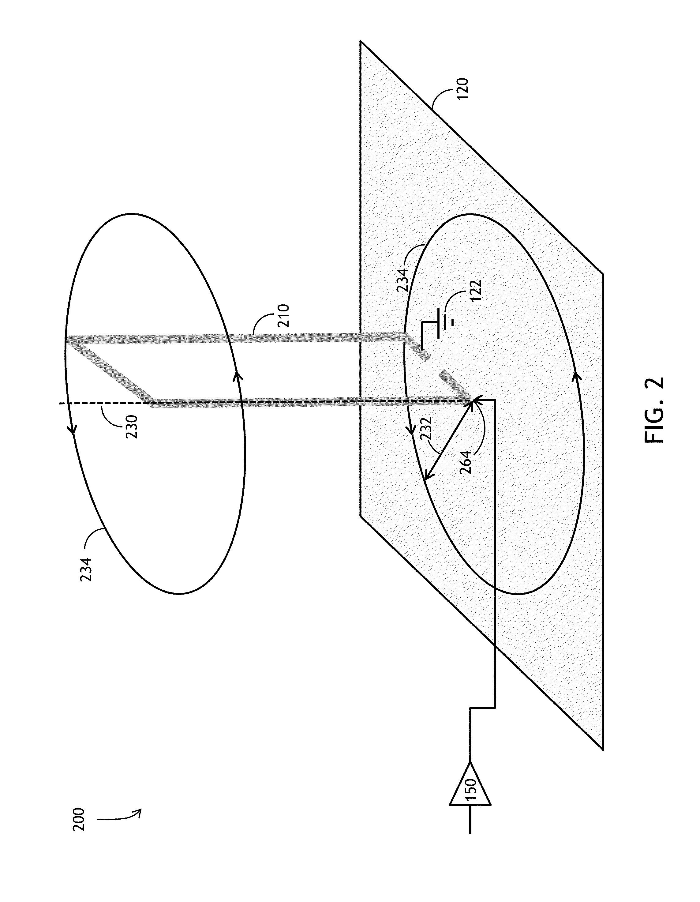
[0031]Embodiments of the present invention are directed to a system and related method for an electrically small loop antenna of variable geometry capable of a harmonically pure resonant radiation pattern over a broadband coverage of frequency selection.

[0032]Embodiments of the present invention additionally permit creation of broadband, electrically small radiators with efficiency previously unattainable through traditional methods. The invention may be utilized in multi-radiator systems and arr...


PUM


Abstract

An antenna system and related method are disclosed for an electrically small antenna of variable geometry capable of a harmonically pure resonant radiation pattern over a broadband coverage of frequency selection. One geometrical embodiment comprises a multiple loop antenna system is configured to radiate a switched signal via the multiple antenna elements to inhibit transmission of any of the harmonics of the signal. An additional geometrical embodiment comprises a cylindrical shell with one or more interior center conductors to overcome radiation resistance and radiate a signal pattern of desirable toroidal shape free from undesirable harmonics.

Description

FIELD OF THE INVENTION[0001]The present invention relates generally to signal transmission and associated antenna structure. More particularly, embodiments of the present invention relate to an antenna system and method providing wideband transmission capability via an electrically small antenna structure.BACKGROUND OF THE INVENTION[0002]Traditional electrically-small antennas (ESA) may enable a broad-band operation from non-resonant loop antennas. Some efforts may employ voltage-mode Class-D power amplifiers (PA) using Radio Frequency Pulse Width Modulation (RF-PWM) to synthesize low-harmonic loop current.[0003]While an improvement over traditional use of Class-AB PA to perform this task, the efficiency of these schemes may be quite low, not exceeding the ratio of the radiation resistance of the loop to twice the resistance (Rds) on of the switching devices. The switching losses of this scheme are expected to further degrade system efficiency.[0004]One such traditional attempt may ...

Claims


Application Information

Patent Timeline
Patent Type & Authority Patents(United States)
IPC IPC(8): H04B1/10H01Q5/00H04B1/04H01Q21/00H03H7/40
CPCH01Q5/0093H04B1/0458H04B1/0475H03F2200/451H03H7/40H01Q21/0056H03F3/2178H01Q7/00
Inventor CRIPE, DAVID W.
Owner ROCKWELL COLLINS INC
Why Eureka
Try Eureka