Electronic device and power-source device

a technology of power supply and power supply device, which is applied in the direction of electrographic process, instruments, transportation and packaging, etc., can solve the problems of secondary battery life, insufficient power supply to make the accepting unit operable, and inability to operate externally

Active Publication Date: 2016-05-24
KONICA MINOLTA BUSINESS TECH INC
View PDF16 Cites 10 Cited by
  • Summary
  • Abstract
  • Description
  • Claims
  • Application Information

AI Technical Summary

Benefits of technology

[0015]It is therefore an object of the present invention to provide an electronic device that can be charged appropriately without occurrence of a memory effect in a secondary battery. It is another object of the present invention to provide a power-source device that can be used suitably in the electronic device.

Problems solved by technology

In such an image forming apparatus, when the capacity of the secondary battery decreases, an amount of power sufficient enough to make the accepting unit operable may not be supplied to the accepting unit, and the accepting unit including the external interface or the like may not accept a processing request for image formation in the waiting state.
When the memory effect occurs in the secondary battery, the external interface may not be operated appropriately since the voltage supplied from the secondary battery thereto decreases.
Furthermore in that case, it may be erroneously judged that the secondary battery has come to the end of life, although in the actuality the secondary battery still has a usable amount of capacity.

Method used


Image

  • Electronic device and power-source device
  • Electronic device and power-source device
  • Electronic device and power-source device

Examples


Embodiment Construction

[0031]The following describes an embodiment of the present invention.

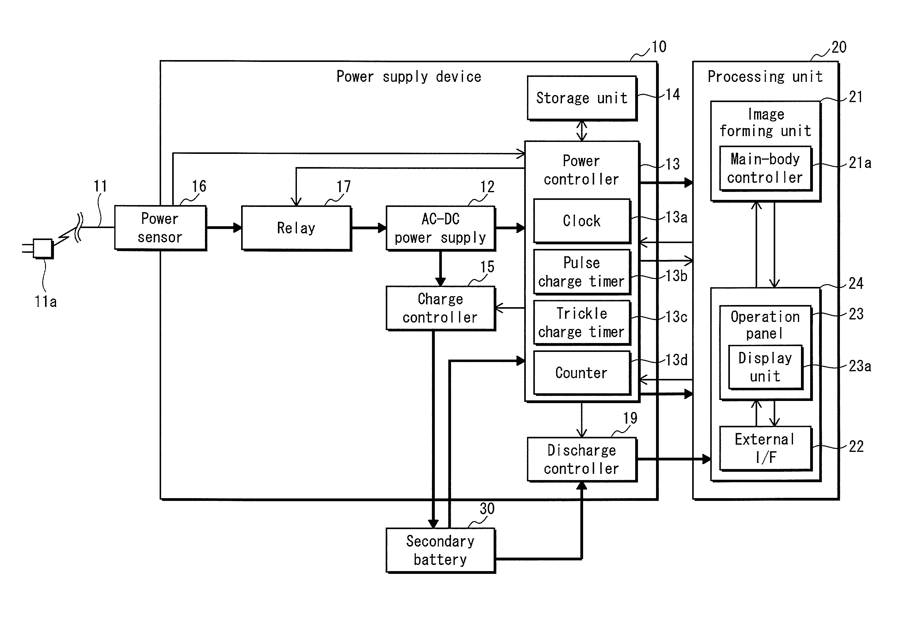
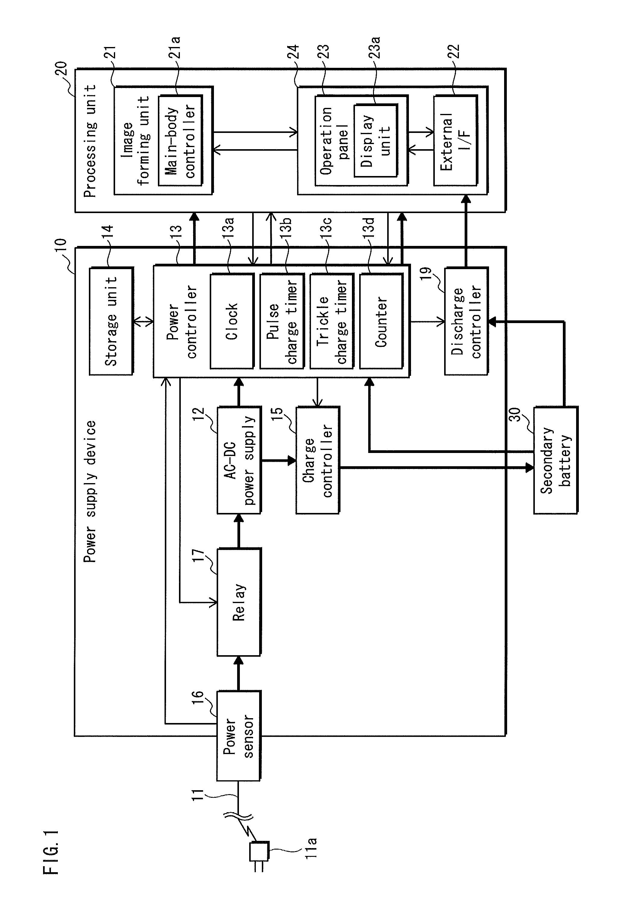
[0032]FIG. 1 is a block diagram illustrating the structure of the image forming apparatus in the embodiment of the present invention. FIG. 1 illustrates an MFP (Multiple Function Peripheral) device, which is a multiple-function copier, as the image forming apparatus of the present embodiment.

[0033]The MFP device includes a processing unit 20 that includes: an image forming unit 21 for forming a toner image on a recording sheet based on the image data; and an accepting unit (an accepting part) 24 for accepting a processing request (an image formation instruction) for the image forming unit 21. The MFP device also includes: a power-source device 10 for performing, for example, a control to supply power, which is supplied from a commercial power source (external power source), to the processing unit 20; and a secondary battery 30 for supplying power to the power-source device 10 and the accepting unit 24 of the proces...


PUM


Abstract

Electronic device comprising: processing unit including accepting part accepting processing request from external device and executing process specified by request; secondary battery connected with external power source; and power-source device transitioning to operating state when request is accepted in waiting state, and transitioning to waiting state when processing unit completes executing process, wherein, in waiting state, power supply from external power source to processing unit is stopped and secondary battery supplies power to accepting part, and in operating state, power is supplied from external power source to processing unit. Power-source device includes controller executing first charge control operation to cause external power source to charge secondary battery when, in operating state, voltage of secondary battery is not higher than threshold, and end executing first charge control operation when transitioning to waiting state, controller updating threshold in response to increase in number of times first charge control operation is executed.

Description

[0001]This application is based on application No. 2012-31424 filed in Japan, the contents of which are hereby incorporated by reference.BACKGROUND OF THE INVENTION[0002](1) Field of the Invention[0003]The present invention relates to an electronic device, such as an image forming apparatus, loaded with a secondary battery, and to a power-source device used in the electronic device.[0004](2) Description of the Related Art[0005]Some electronic devices use, in parallel, (i) power supplied from a commercial power source (external power source) and (ii) power supplied from a secondary battery such as a nickel hydride battery.[0006]For example, the following MFP (Multiple Function Peripheral) device, a type of electronic device, has been proposed. That is to say, the MFP device includes a processing unit that includes: an image forming unit for executing an image forming operation; and an accepting unit including an external interface or the like for accepting a processing request (instr...

Claims


Application Information

Patent Timeline
Patent Type & Authority Patents(United States)
IPC IPC(8): H02J4/00G03G15/00H02J7/00H02J7/02
CPCH02J7/007G03G15/5004G03G15/80H02J4/00H02J7/0075G03G2215/00126G03G2215/00983Y10T307/696H02J7/0069
Inventor HASEBE, TAKASHIHIRAGUCHI, HIROSHIYAMAMOTO, MINEOTAMURA, TOMONOBUTATSUMOTO, YUHEI
Owner KONICA MINOLTA BUSINESS TECH INC
Why Eureka
Try Eureka