
Device for control of data transfer in local area network

a technology for local area networks and data transfer, applied in the direction of electrical equipment, network topologies, wireless commuication services, etc., can solve the problems of increasing the increasing the risk of interference with other rf systems operating in the same frequency band, and increasing the overall height and size of devices. , to achieve the effect of alleviating, eliminating, and reducing the risk of interferen

Active Publication Date: 2016-05-24
SONY CORP
View PDF45 Cites 9 Cited by
  • Summary
  • Abstract
  • Description
  • Claims
  • Application Information

AI Technical Summary

Benefits of technology

[0008]With the above description in mind, then, an aspect of the present invention is to provide a wearable electronic communication device comprising a device in the form of a hardware assembly, for control of data transfer between wearable mobile electronic communication devices that can be used in close proximity to a body of a user, and / or in partial or entire / full contact with the user's body, which seek to mitigate, alleviate, or eliminate one or more of the above-identified deficiencies in the art and disadvantages singly or in any combination.
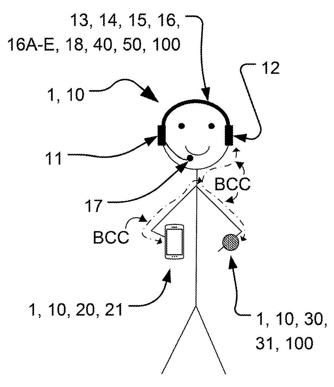
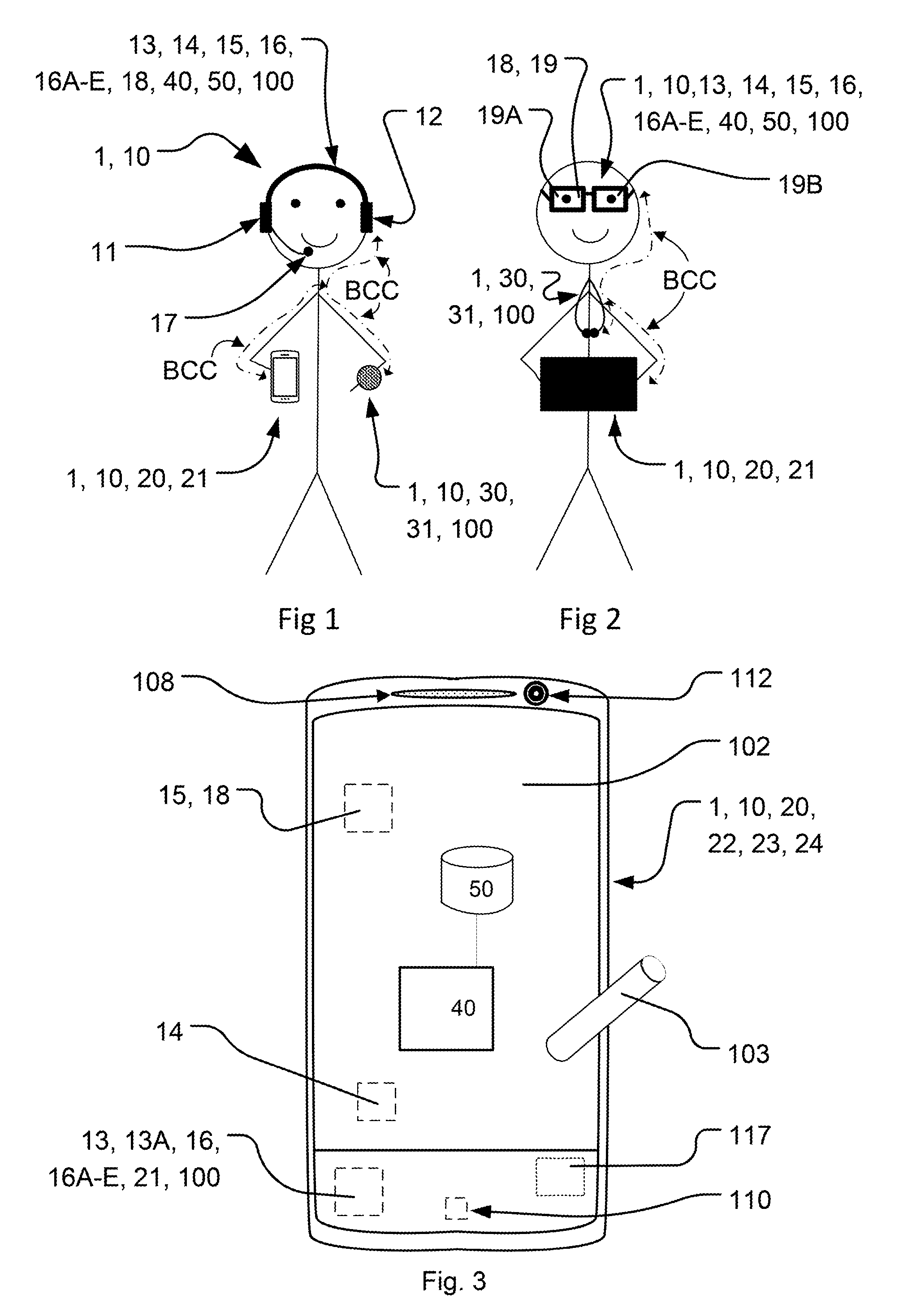
[0009]These and further objects are achieved by a device in the form of a hardware assembly and a mobile / wearable device comprising such a hard ware assembly device, which devices are adapted to cooperate in and with a system and a local / personal / body area network for controlling data transfer between these inventive wearable devices and at least one, two, three or more portable electronic communication devices. The hardware assembly device and mobile / wearable device according to the invention comprises at least one sensor and / or electrode and / or antenna being adapted for both Body-Coupled / -Based Communication (BCC / BBC) and short-range wireless communication by having a capacity to both detect if the mobile / wearable device is on a body of an user and to receive and transmit BCC / BBC signals as one physical entity common for both functions.
[0023]The advantages of the above invention and aspects are for example the following. One advantage is that the wearable electronic communication device and the inventive device in the form of a hardware assembly with an antenna and electrode in one common entity or hardware for both BCC and capacitance check makes the wearable device smaller. Another advantage is that the wearable electronic communication device and the inventive device in the form of a hardware assembly with an antenna and electrode in one common entity or hardware for both BCC and capacitance check makes more space in the interior of the wearable device. This increased inner space is available for further hardware or use without increasing its size, i.e. without increasing the dimensions and / or envelope surface and / or footprint area of the wearable device. Furthermore, the power required for enabling and operating the hardware assembly device and the wearable device according to the invention is also negligible or low. The invention also enables to detect when the wearable device, e.g. a tablet / smartphone / wristlet and / or headset / visors are on the same body by means of one and the same antenna and electrode, no separate antenna or electrode is necessary for this. The inventive devices reduce the number of components and simplify associated circuitry when built and used. The inventive hard ware assembly device reduces costs for implementation of such systems in wearable electronic communication devices. The necessary space for existing hardware is also reduced by the inventive device enabling improved cooling. The necessary space for existing hardware is also reduced by the inventive device making room for additional components without increasing the size of the electronic wearable device. The inventive device with the body capacitance measurement and the BCC implemented by means of one and the same component and by means of processing circuitry comprising differing impedances when using the common electrode for body capacitance measurement and when using the common electrode for BCC means that processing circuitry for the BCC are not negatively affected or loaded by power dissipation due to the capacitance measurement. Furthermore, RF techniques exhibit by nature radiation patterns which field-strengths can vary largely in different directions from its source and which relates to device and antenna configurations as well as shadowing and absorption effects present in the close vicinity to the RF source. In some applications, it is however important to be able to control and limit the radiating field outside of the users body to less than a few cm range and hence the BCC / BAN technique of the invention greatly can serve this purpose.

Problems solved by technology

The radio-frequency (RF) techniques have some drawbacks, e.g. there might be a limited operating time due to relatively high power consumption of the RF transceiver, there is a risk of interference with other RF systems operating in the same frequency band.
Hence, in many cases, the available volume and envelope surfaces of housings for such wearable devices are getting smaller, or at least the height or thickness of a new model of such a device is often reduced, meaning that overall heights and sizes and foot print areas of associated hardware, e.g. antennas, sensors, and integrated circuits, inside the wearable devices undergo delicate optimizations of available space as more and more hardware components often are to be introduced in such a device.
The surface area of the hardware inside the housing of a wearable electronic communication device and the housing itself also involves an increased cost for the manufacturer of the device as any additional volume or area of the device in general demand more effort and material at manufacture.
Yet further, when a wearable electronic device is to be equipped with additional hardware, such as BAN / BCC antennas and capacitive sensors, the handling and size of the portable electronic device are compromised as known hardware, due to their shape, require a certain minimum height and foot-print area inside such a device, but also externally of the device, i.e. the outer envelope surface is also affected by the above delicate considerations of dimensions.

Method used


Image

  • Device for control of data transfer in local area network
  • Device for control of data transfer in local area network
  • Device for control of data transfer in local area network

Examples


Embodiment Construction

[0037]Various aspects of the invention will hereinafter be described in conjunction with the appended drawings to illustrate but not to limit the invention. Variations of the inventive aspects are not restricted to the specifically shown embodiments, but are applicable on other variations of the invention. Like designations denote like elements.

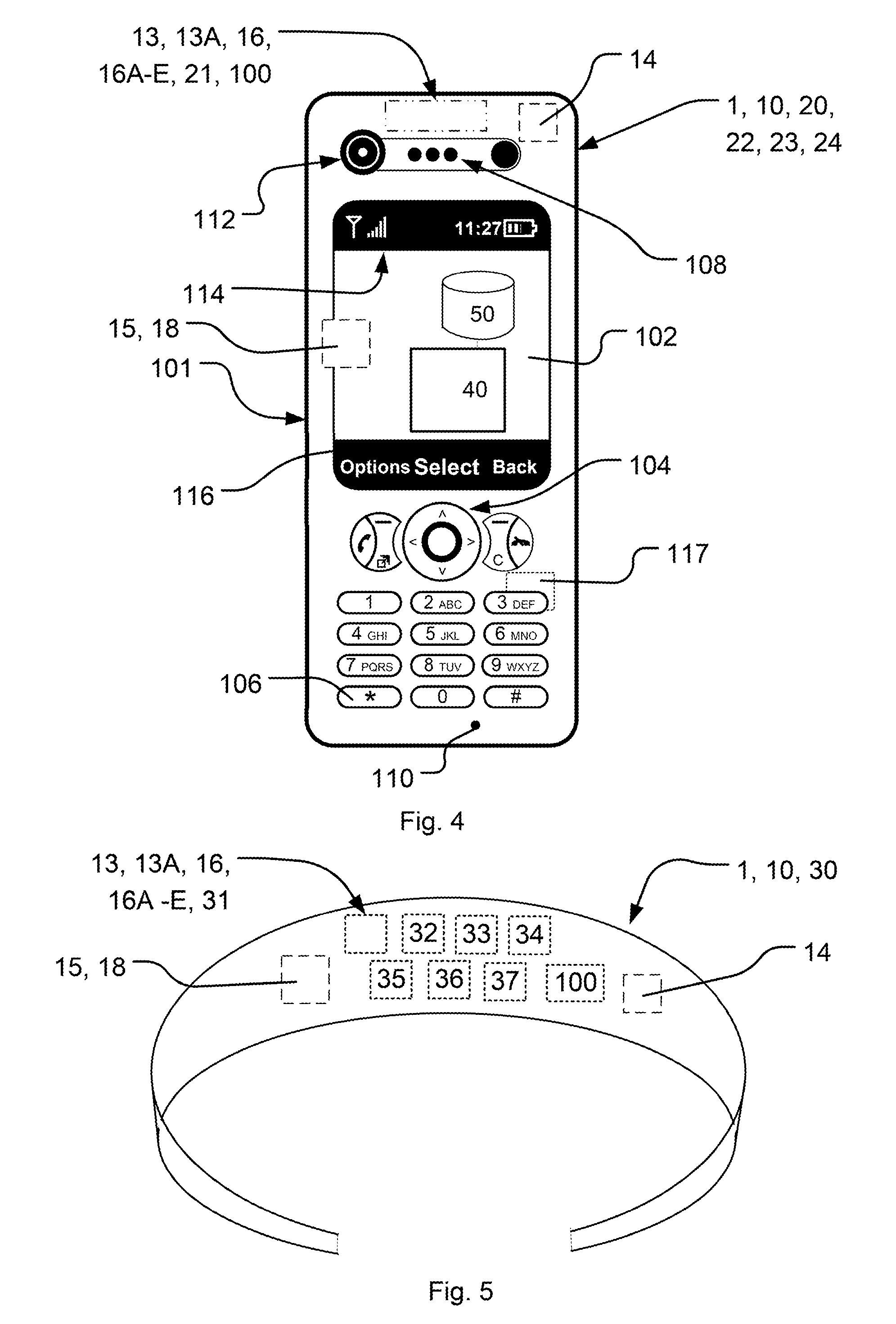
[0038]Embodiments of the present invention will be exemplified using a mobile communication device such as a mobile phone and / or a wearable device such as a wristlet, headphone or visors or the like. However, it should be appreciated that the invention is as such equally applicable to electronic devices which have touch detection capabilities. Examples of such devices may for instance be any type of mobile phone, smartphone, laptop (such as standard, ultra-portables, netbooks, and micro laptops) handheld computers, portable digital assistants, tablet computers, touch pads, gaming devices, accessories to mobile phones, e.g. wearables in the fo...


PUM


Abstract

The present invention concerns wearable electronic communication devices (100) for control of data transfer in a personal area network. The wearable device is adapted for Body Coupled Communication in close proximity to a person's body. The wearable device comprises an antenna adapted for Body Coupled Communication and a capacitance sensor indicating that the wearable device is in close proximity to the body of the person or even in contact with the body or not. The invention also concerns a portable electronic communication device comprising the inventive wearable device for cooperation with at least a second portable electronic communication device in a personal area network.

Description

CROSS-REFERENCE TO RELATED APPLICATIONS[0001]This application is a continuation-in-part of U.S. patent application Ser. No. 14 / 318,025, filed 27 Jun. 2014, the disclosure of which is hereby incorporated by reference herein.TECHNICAL FIELD[0002]The present invention relates to portable and wearable electronic communication devices and hardware assembly devices used in such wearable electronic communication devices for data transfer and control of said data transfer close to and / or in contact with a person's body, wherein the inventive device is a wearable electronic communication device adapted for both wireless and Body Coupled Communication with at least one further portable electronic communication device of a system in a personal area network.BACKGROUND ART[0003]Earpieces, earphones, headsets, headphones or other handsfree solutions are commonly utilized to keep the sound private and / or to facilitate multitasking when listening to music, talking in the phone, getting body functio...

Claims


Application Information

Patent Timeline
Patent Type & Authority Patents(United States)
IPC IPC(8): H04B5/00H04B13/00H04W4/00H04W84/10H04W4/80
CPCH04W4/008H04B5/0012H04B13/005H04W84/10H04B5/0031H04W4/80
Inventor TARNHED, KRISTIANANG.STRAND, PERAGARDH, KAREBOLIN, THOMASRODZEVSKI, ALEKSANDARBENGTSSON, HENRIK
Owner SONY CORP
Learn More