
Signal processing device, radar apparatus, target object method

a technology of radar and signal processing device, applied in measurement devices, using reradiation, instruments, etc., can solve problems such as inability to improve signal-to-noise ratio (s/n) and ratio (s/c) as sufficiently, and doppler processing

Active Publication Date: 2016-05-31
FURUNO ELECTRIC CO LTD
View PDF14 Cites 1 Cited by
  • Summary
  • Abstract
  • Description
  • Claims
  • Application Information

AI Technical Summary

Benefits of technology

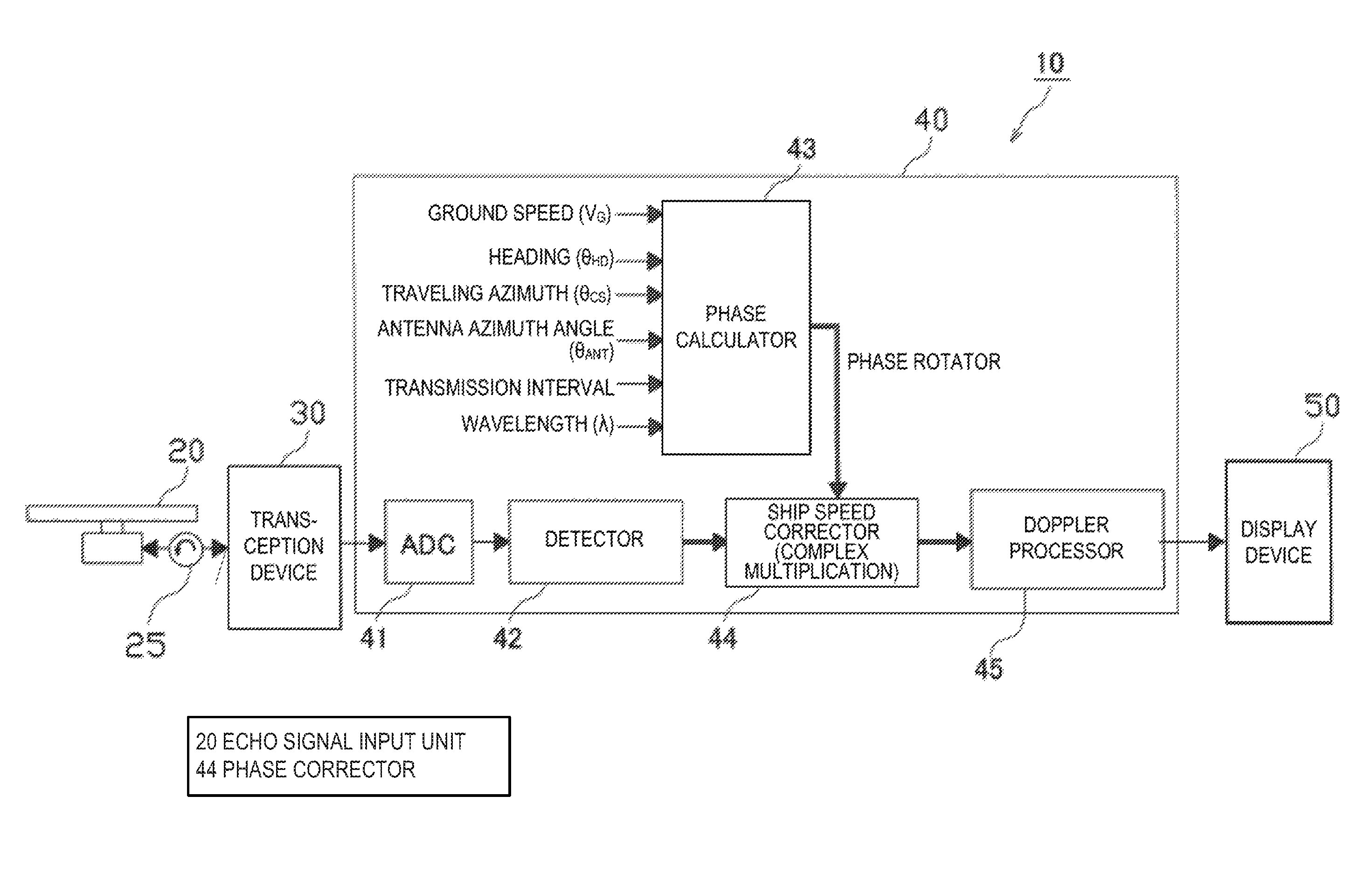
[0008]The present invention is made in view of the above situation, and aims to provide a device that can improve S / C and S / N by Doppler processing even in a detection apparatus, such as a radar apparatus adopting a staggered trigger scheme.
[0011]Moreover, in this aspect of the present invention, under a condition that the stagger processing is applied, the phase change amount based on a shifted amount from a transmission timing based on a predetermined cycle of the transmitted pulse signal. The Doppler processing is performed by taking the phase change amount into consideration. The Doppler processing is performed on the complex reception signals obtained based on the staggered trigger repetitively pulsed signals, and thus, the phase error due to both the relative speed of the specific object and the stagger processing can be removed mostly.
[0012]According to the present invention, in the Doppler processing in, for example, a radar apparatus adopting the starred trigger scheme, interruption of improvements in S / C and S / N due to the interval of the transception of the pulse signal being unequal between sweeps can be reduced.

Problems solved by technology

However, in the case where the stagger processing is performed in the radar apparatus to which the Doppler processing is applied, if a relative speed of the other ship with respect to the ship increases, a signal-to-clutter ratio (S / C) and a signal-to-noise ratio (S / N) may not be able to improve as sufficiently as expected in the Doppler processing, due to the influence of the stagger processing.

Method used


Image

  • Signal processing device, radar apparatus, target object method
  • Signal processing device, radar apparatus, target object method
  • Signal processing device, radar apparatus, target object method

Examples


Embodiment Construction

(1) Analyzation of Problems

[0021]The present inventors have noticed that when stagger processing is performed in a detection apparatus, such as a radar apparatus set to perform Doppler processing, improvements of S / C and S / N that should originally be obtained by the Doppler processing cannot be achieved sufficiently. Therefore, the present inventors have discussed about the cause thereof first, and successfully determined the cause. Hereinafter, the description is given about the analyzation of the problems.

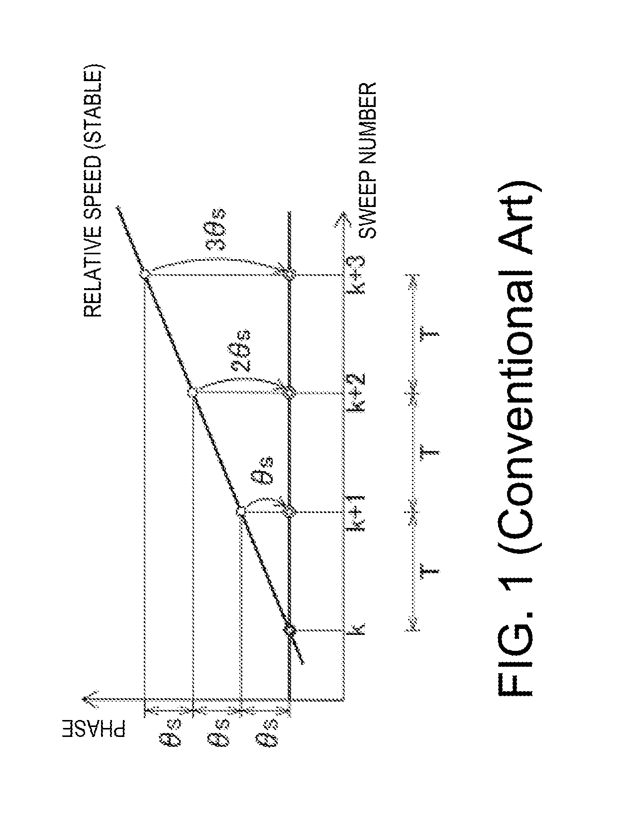
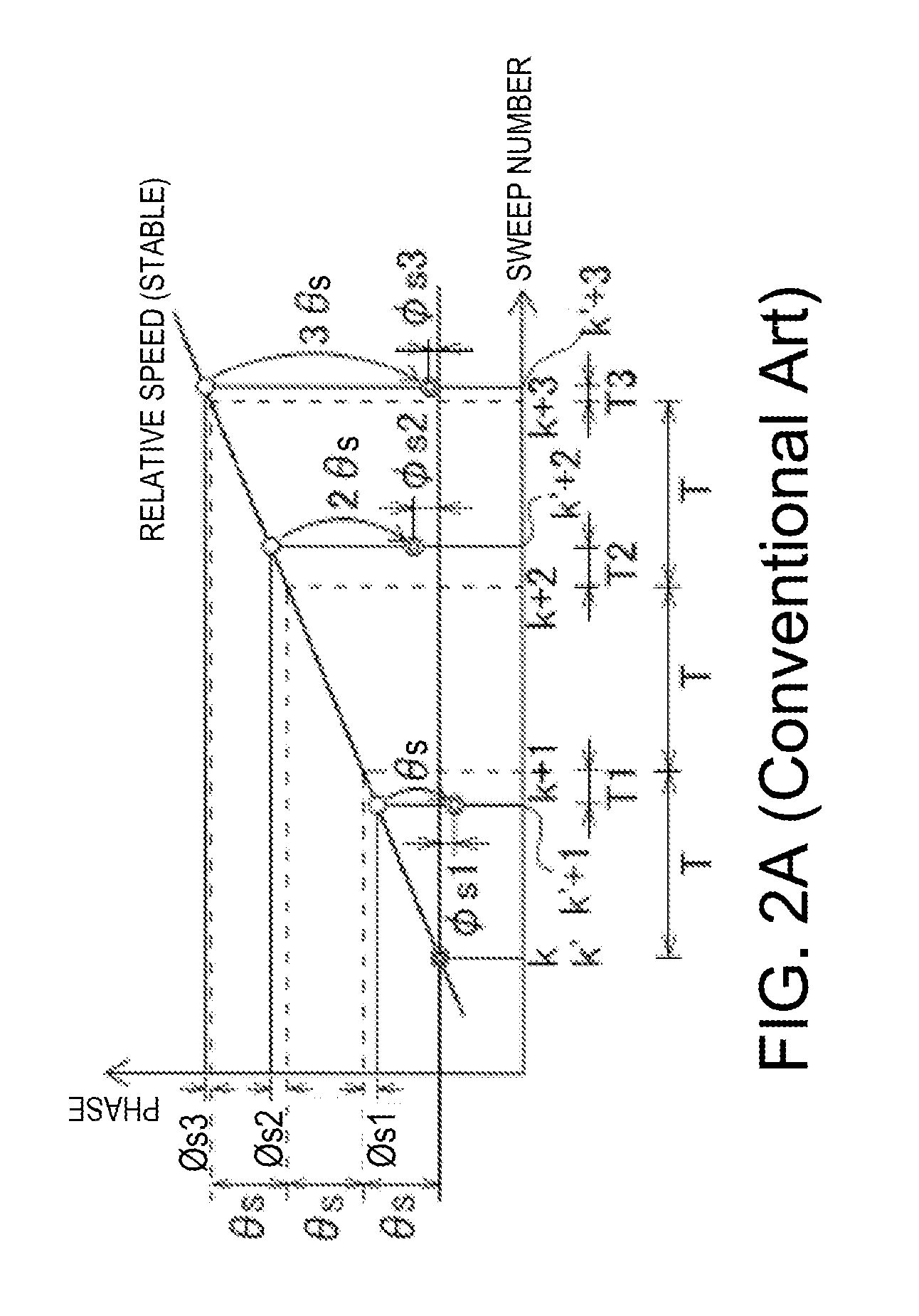
[0022]When two processing of the Doppler processing and stagger processing are applied to one radar apparatus equipped in a ship concerned, there will be a concern of interrupting improvements of the signal-to-clutter ratio (S / C) and the signal-to-noise ratio (S / N) in the Doppler processing as a relative speed of another ship with respect to the ship concerned increases. First, the description is given about an influence on the Doppler processing by the stagger processing with re...


PUM


Abstract

A signal processing device is provided. The device includes an echo signal input unit for receiving echo signals resulted from transmission signals reflected on an object. The transmission signals are transmitted from a transmission source at transmission timings at predetermined time intervals, at least one of the transmission timings shifted from the other timings in time. The device includes a complex reception signal generator for generating complex reception signals, a phase calculator for calculating a phase change amount of the complex reception signals with respect to a reference phase, a phase corrector for phase-correcting the complex reception signals and outputting the corrected signals, and a Doppler processor for performing Doppler processing on the corrected signals and outputting the Doppler-processed signals as Doppler echo signals of the object.

Description

CROSS-REFERENCE TO RELATED APPLICATION(s)[0001]The application claims priority under 35 U.S.C. §119 to Japanese Patent Application No. 2012-195154, which was filed on Sep. 5, 2012, the entire disclosure of which is hereby incorporated by reference.TECHNICAL FIELD[0002]The present invention generally relates to a signal processing device for processing an echo signal in a detection apparatus, such as a radar apparatus, the radar apparatus for detecting a target object by transceiving an electromagnetic wave, and a method of processing a signal in these device and apparatus. The signal processing device and method of the present invention are particularly applied to the detection apparatus, such as the radar apparatus, using a staggered trigger scheme.BACKGROUND OF THE INVENTION[0003]Radar apparatuses detect target objects (e.g., aircrafts and ships) generally by transmitting pulses of electromagnetic waves from antennas and receiving reflection waves from the target objects from the ...

Claims


Application Information

Patent Timeline
Patent Type & Authority Patents(United States)
IPC IPC(8): G01S13/93G01S13/50G01S13/524G01S13/58
CPCG01S13/505G01S13/5242G01S13/582
Inventor ASADA, YASUNOBUOKUNISHI, AKIRADAI, KOJITAKEMOTO, SAE
Owner FURUNO ELECTRIC CO LTD
Learn More