
Mitigating main crossbar load using dedicated connections for certain traffic types

Active Publication Date: 2016-06-14
NVIDIA CORP
View PDF45 Cites 3 Cited by
  • Summary
  • Abstract
  • Description
  • Claims
  • Application Information

AI Technical Summary

Benefits of technology

The parallel processing unit described in this patent has a control crossbar unit that improves the transmission of different types of control information. This reduces the load on the main crossbar unit and ensures efficient use of bandwidth. This results in faster processing and better performance of the parallel processing unit.

Problems solved by technology

Certain connections also may or may not implement flow control mechanisms.

Method used


Image

  • Mitigating main crossbar load using dedicated connections for certain traffic types
  • Mitigating main crossbar load using dedicated connections for certain traffic types
  • Mitigating main crossbar load using dedicated connections for certain traffic types

Examples


Embodiment Construction

[0026]In the following description, numerous specific details are set forth to provide a more thorough understanding of the present invention. However, it will be apparent to one of skill in the art that the present invention may be practiced without one or more of these specific details. In other instances, well-known features have not been described in order to avoid obscuring the present invention.

System Overview

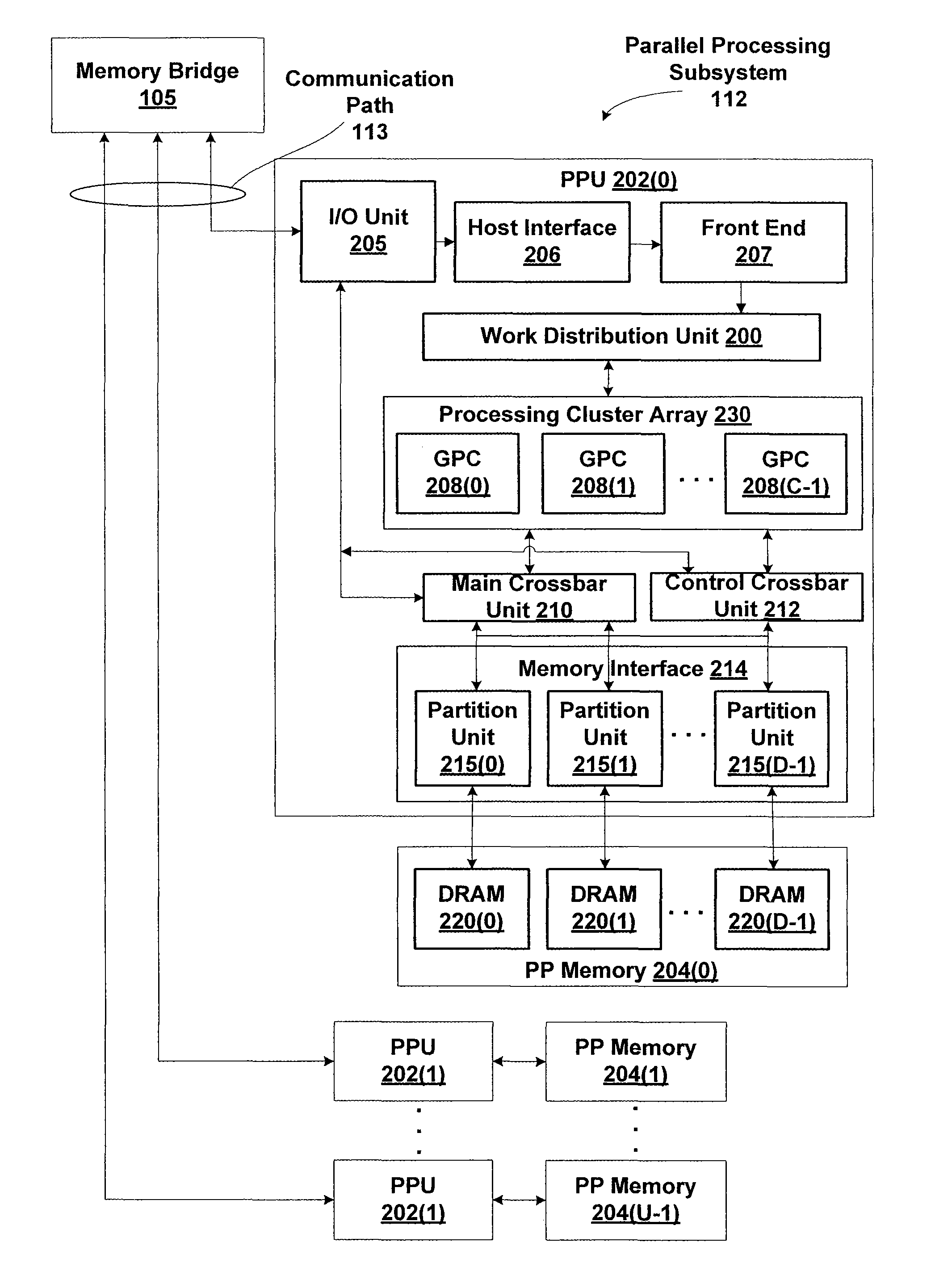
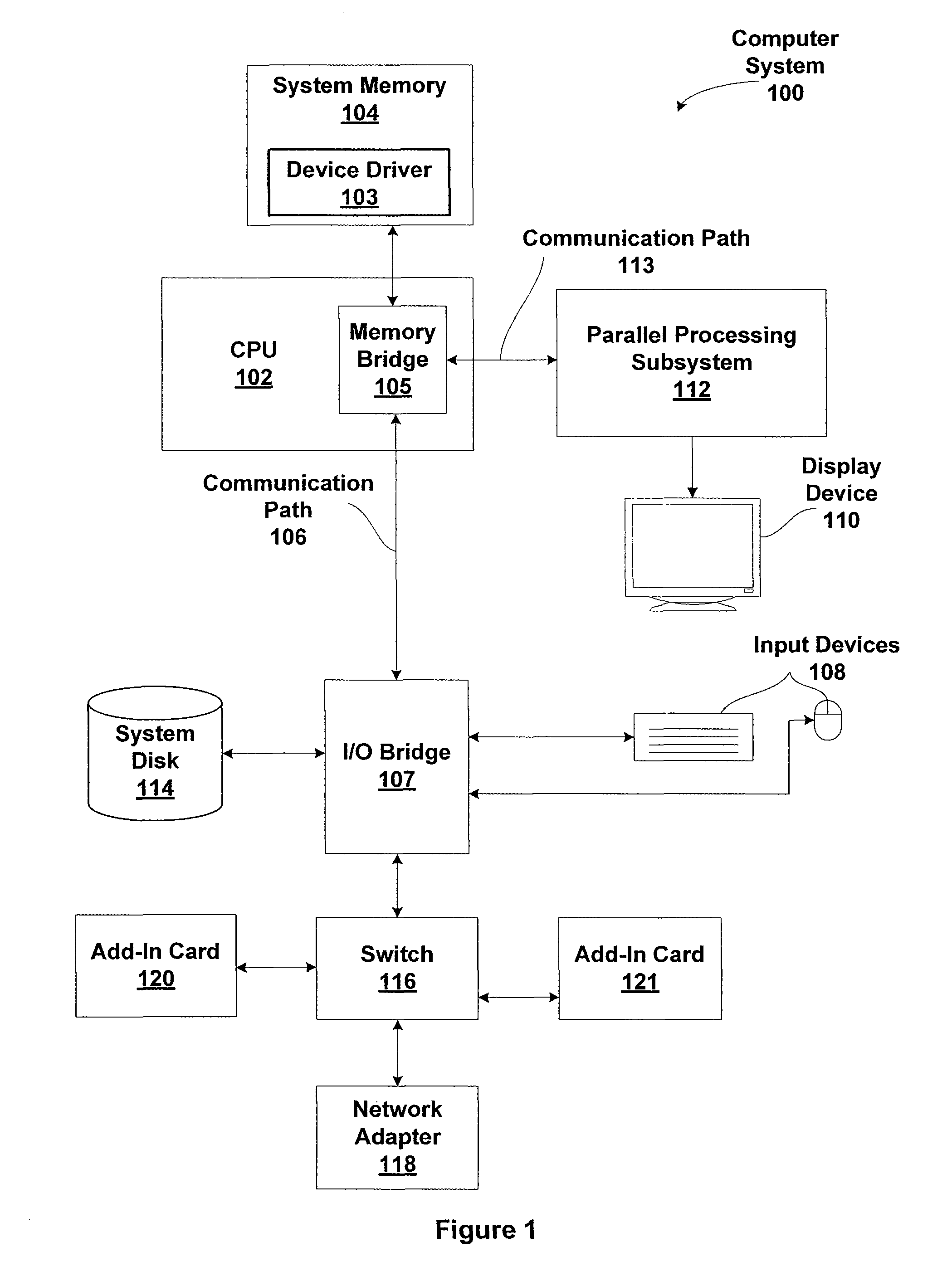
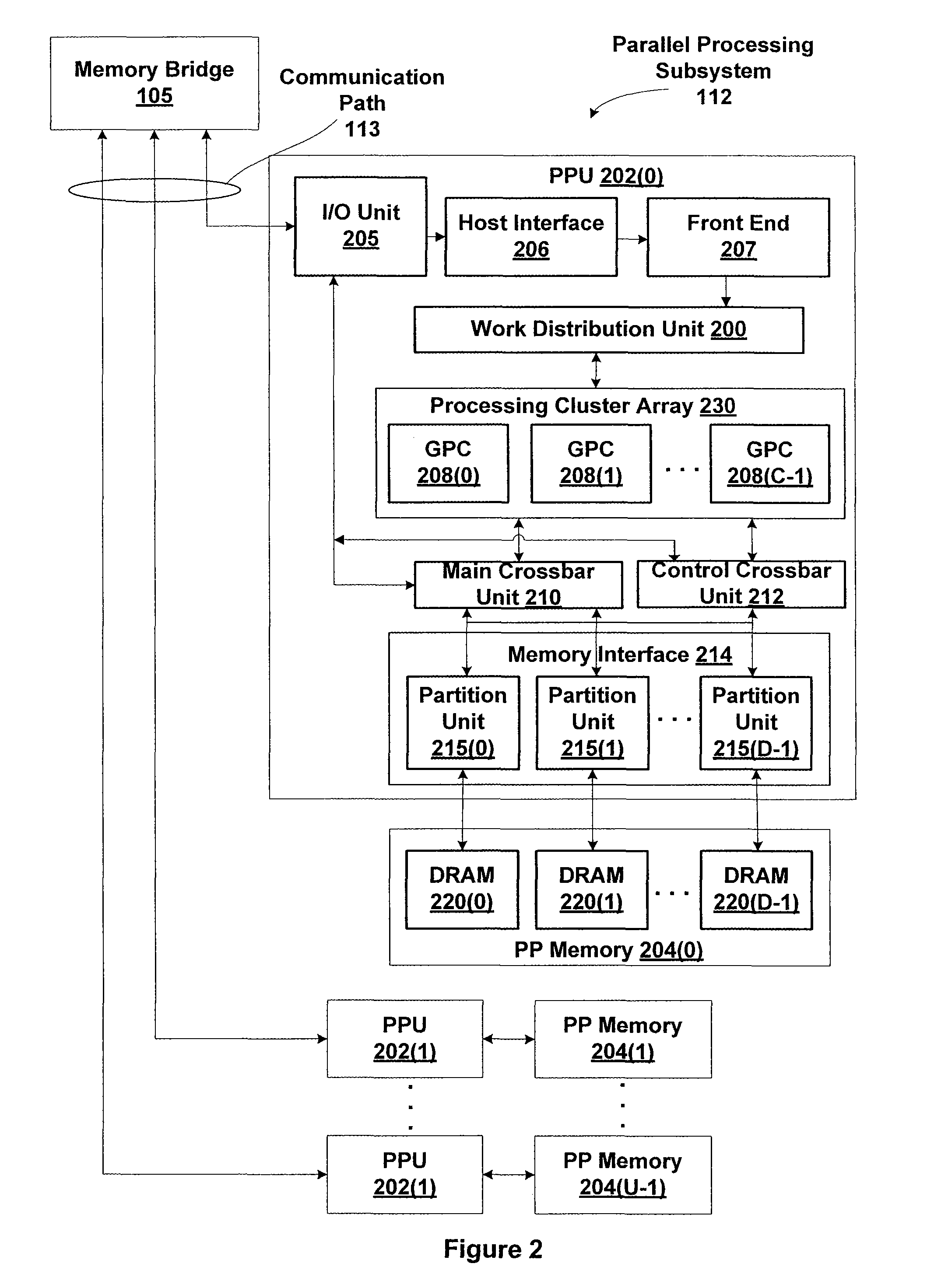
[0027]FIG. 1 is a block diagram illustrating a computer system 100 configured to implement one or more aspects of the present invention. Computer system 100 includes a central processing unit (CPU) 102 and a system memory 104 communicating via a bus path through a memory bridge 105. Memory bridge 105 may be integrated into CPU 102 as shown in FIG. 1. Alternatively, memory bridge 105, may be a conventional device, e.g., a Northbridge chip, that is connected via a bus to CPU 102. Memory bridge 105 is connected via communication path 106 (e.g., a HyperTransport link) to an I...


PUM


Abstract

One embodiment of the invention sets forth a control crossbar unit that is designed to transmit control information from control information generators to destination components within the computer system. The control information may belong to various traffic paradigms, such as short-latency data traffic, narrow-width data traffic or broadcast data traffic. The physical connections within the control crossbar unit are categorized based on the different types of control information being transmitted through the control crossbar unit. The physical connections belong to the following categories: one-to-one (OTO) connections, one-to-many (OTM) connections, valid-to-one (VTO) connections, valid-to-many (VTM) connections wire-to-one (WTO) connections and wire-to-many (WTM) connections.

Description

BACKGROUND OF THE INVENTION[0001]1. Field of the Invention[0002]The present invention relates generally to the field of data transport management and, more specifically, to mitigating main crossbar load using dedicated connections for certain traffic types.[0003]2. Description of the Related Art[0004]In many computing systems, a data transport mechanism is responsible for the physical transfer of data from a source component to a destination component. The source and destination components may include system elements, such as computation engines and memory subsystems. As is well known, the bandwidth of the data transport mechanism is the rate of data transfer between the source and destination components, measured in bits per clock cycle. As is also well known, data is transmitted to and from components within a computing system in collections of bits, where a collection of bits is referred to as a ‘data packet.’ In general, the size of a single data packet may not exceed the bandwi...

Claims


Application Information

Patent Timeline
IPC IPC(8): G06F13/00G06F9/38
CPCG06F9/38G06F13/00G06F15/7825
Inventor MRAZEK, DANELIU, YONGXIANGTANG, YIN FUNGGLASCO, DAVID
Owner NVIDIA CORP
Learn More