Evaporated fuel treatment apparatus

a technology of evaporation fuel and treatment apparatus, which is applied in the direction of machines/engines, liquid transfer devices, separation processes, etc., can solve the problems of difficult to improve the performance of preventing the blowing by of fuel components to the atmosphere, and the port side cannot be adequately suppressed, so as to reduce the blowing by of fuel components

Active Publication Date: 2016-06-28
AISAN IND CO LTD
View PDF19 Cites 1 Cited by
  • Summary
  • Abstract
  • Description
  • Claims
  • Application Information

AI Technical Summary

Benefits of technology

[0006]Thus, an object of the present invention is to provide an evaporated fuel treatment apparatus that can reduce blow-by of fuel components to the outside from an atmosphere port more than the conventional canister.
[0007]The present invention is provided with a main adsorbent layer and, in a region on an atmosphere port side of the main adsorbent layer, three or more adsorbent layers which are different from the main adsorbent layer as well as separating portions that separate the adsorbent layers that are adjacent to each other. By making the volume of at least one separating portion among these separating portions larger than the total of the volumes of adsorbent layers that sandwich the separating portion therebetween, diffusion from the separating portion to the atmosphere port side can be suppressed more than in the conventional canister, and the amount of blow-by to the atmosphere can be decreased and the blow-by performance can be improved in comparison to the conventional canister.

Problems solved by technology

In the canister according to the conventional technology, because a volume of a separating portion is less than a volume of adjacent adsorbent layers and the separating portion does not have an adequate volume, there has been the problem that diffusion of fuel components to the atmosphere port side cannot be adequately suppressed by the separating portion, and it is difficult to improve the performance with respect to preventing blow-by of fuel components to the atmosphere.

Method used


Image

  • Evaporated fuel treatment apparatus
  • Evaporated fuel treatment apparatus
  • Evaporated fuel treatment apparatus

Examples


embodiment 1

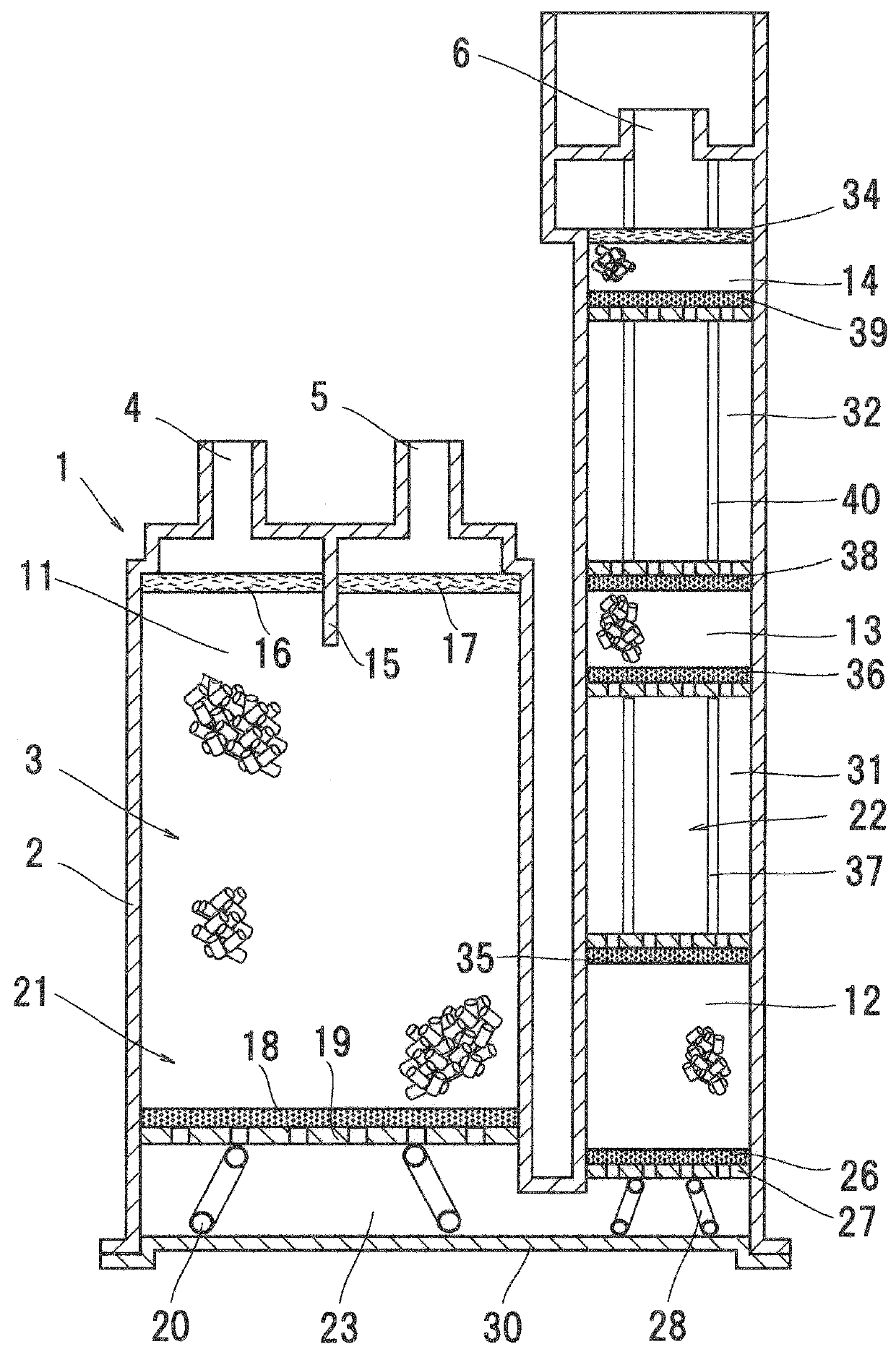
[0022]FIG. 1 illustrates Embodiment 1 according to the present invention.

[0023]As shown in FIG. 1, an evaporated fuel treatment apparatus 1 according to the present invention includes a casing 2. In the casing 2, a passage 3 circulating fluid is formed. A tank port 4 and a purge port 5 are formed at an end of the passage 3 in the casing 2, and an atmosphere port 6 is formed at the other end thereof.

[0024]In the passage 3, four adsorbent layers filled with adsorbent adsorbing evaporated fuel components, that is, a first adsorbent layer 11, a second adsorbent layer 12, a third adsorbent layer 13, and a fourth adsorbent layer 14, are arranged in series. In the present embodiment, activated carbon is used as the adsorbent.

[0025]As shown in FIG. 1, a main chamber 21 communicating with the tank port 4 and the purge port 5, and an auxiliary chamber 22 communicating with the atmosphere port 6 are formed in the casing 2. The main chamber 21 and the auxiliary chamber 22 are partitioned by par...

embodiment 2

[0054]In Embodiment 1 a configuration is adopted in which the volume Vβ of the first separating portion 31 is made smaller than the total of the volume V2 of the second adsorbent layer 12 and the volume V3 of the third adsorbent layer 13 that are the adsorbent layers that sandwich the first separating portion 31. However, a configuration may also be adopted in which the volume Vβ of the first separating portion 31 is set so as to be larger than the sum total of the volume V2 of the second adsorbent layer 12 and the volume V3 of the third adsorbent layer 13 that are the adsorbent layers that sandwich the first separating portion 31.

[0055]For example, with respect to the configuration shown in FIG. 1, the volume Vα of the second separating portion 32 is set to 200 ml, the volume Vβ of the first separating portion 31 is set to 180 ml, a volume Vγ of the space 23 is set to 410 ml, the volume V4 of the fourth adsorbent layer 14 is set to 30 ml, the volume V3 of the third adsorbent layer ...

embodiment 3

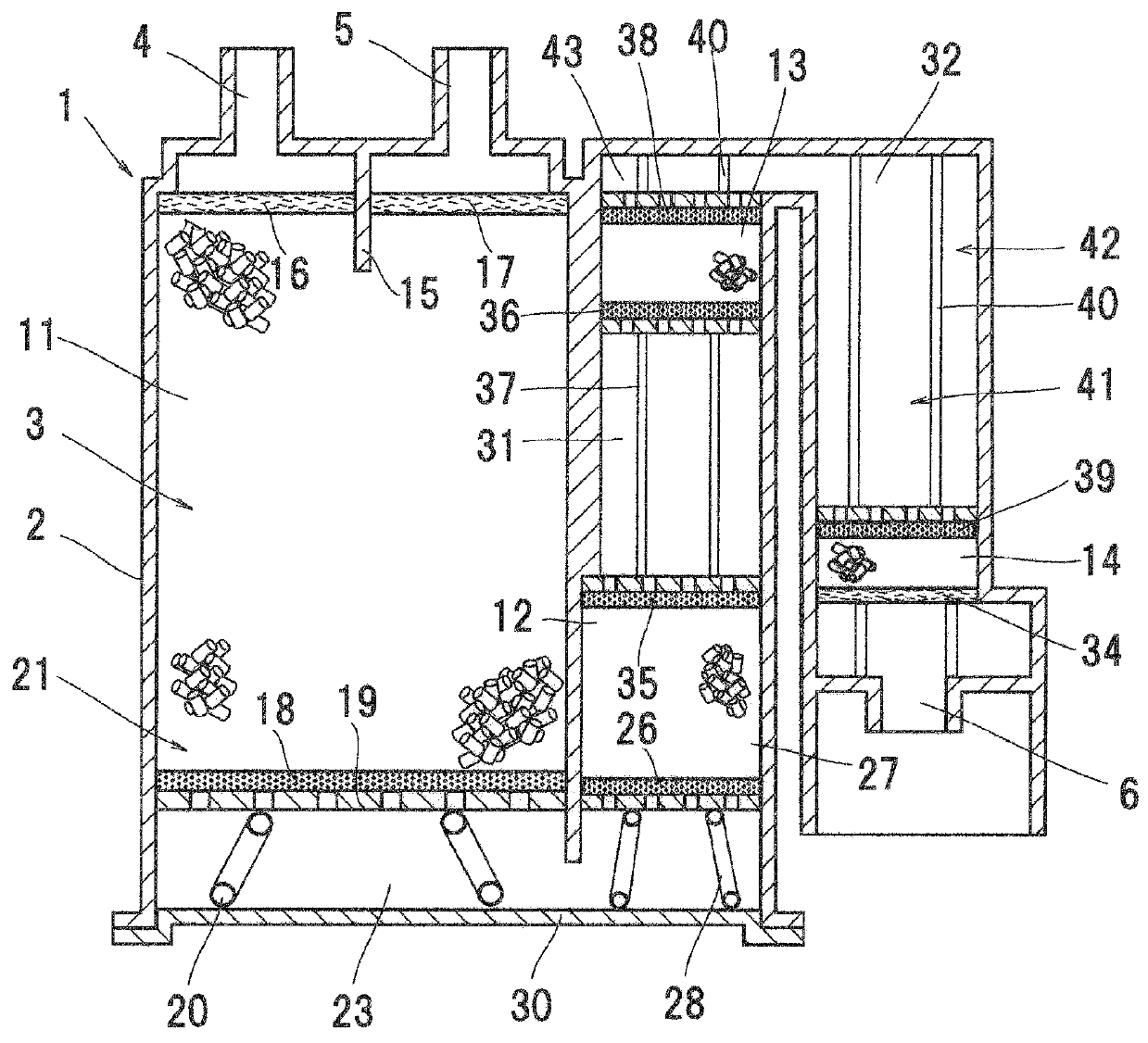
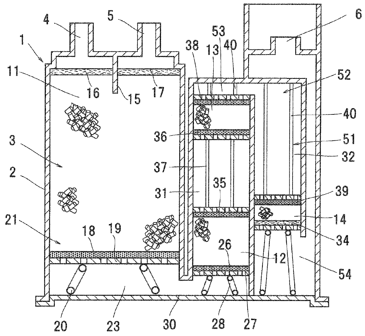
[0059]In Embodiments 1 and 2, the U-shaped passage 3 that is turned in the opposite direction once in the space 23 is formed in the casing 2. However, for example, as shown in FIG. 2, the passage in the casing 2 may also be configured as a passage 41 that is formed in an N-shape that is turned in the opposite direction twice in the casing 2.

[0060]The structure of the main chamber 21 of Embodiment 3 is the same as that of the main chamber 21 in Embodiments 1 and 2.

[0061]In Embodiment 3, an auxiliary chamber 42 that corresponds to the region of the present invention is formed in a U-shape that is turned in the opposite direction in a space 43. One end of the auxiliary chamber 42 communicates with the space 23, and the atmosphere port 6 is provided at the other end thereof.

[0062]The second adsorbent layer 12 and the third adsorbent layer 13 that are the same as in Embodiment 1 are provided between the spaces 23 and 43 in the auxiliary chamber 42. The first separating portion 31 is prov...


PUM

PropertyMeasurementUnit
volume V3aaaaaaaaaa
volume V3aaaaaaaaaa
volume V3aaaaaaaaaa

Abstract

An evaporated fuel treatment apparatus includes a passage circulating fluid being formed therein, a tank port and a purge port being formed at one end side of the passage, and an atmosphere port being formed at another end side of the passage. At least four adsorbent layers in which adsorbent adsorbing fuel components is filled are provided in the passage. The evaporated fuel treatment apparatus has a main adsorbent layer and a region provided on an atmosphere port side of the main adsorbent layer. At least three adsorbent layers that are different from the main adsorbent layer, and separating portions that separate the adsorbent layers which are adjacent to each other are provided in the region. The volume of at least one separating portion in the region is made larger than a total of the volumes of adsorbent layers that sandwich the separating portion therebetween.

Description

BACKGROUND OF THE INVENTION[0001]1. Field of the Invention[0002]The present invention relates to an evaporated fuel treatment apparatus.Background Art[0003]Conventionally, to prevent evaporated fuel from being released to the atmosphere from a fuel tank of an automobile or the like, an evaporated fuel treatment apparatus (hereunder, also referred to as a “canister”) is used that temporarily adsorbs fuel components contained in evaporated fuel.[0004]As such the canister, there is known a canister that has a casing in which a passage circulating a fluid is formed, a tank port and a purge port are formed at one end of the passage, and an atmosphere port is formed at the other end thereof. Inside the passage of the casing, four adsorbent layers filled with activated carbon are arranged in series, and a space in which activated carbon is not filled is formed between adjacent adsorbent layers (see JP-A-2007-146793).[0005]In the canister according to the conventional technology, because a ...

Claims


Application Information

Patent Timeline
Patent Type & Authority Patents(United States)
IPC IPC(8): F02M25/08B01D53/04B67D7/04
CPCF02M25/0854B01D53/0407B01D2253/102B01D2259/4516B01D2259/4566B67D7/0476
Inventor TAKESHITA, SHINYAYAMAMOTO, NORIHISA
Owner AISAN IND CO LTD
Why Eureka
Try Eureka