Solar receiver with natural circulation for generating saturated steam

a solar receiver and natural circulation technology, applied in mechanical equipment, machines/engines, lighting and heating apparatus, etc., can solve the problems of not facilitating natural circulation and much smaller dimensions handled

Active Publication Date: 2016-06-28
ABENGOA SOLAR NEW TECH SA
View PDF32 Cites 0 Cited by
  • Summary
  • Abstract
  • Description
  • Claims
  • Application Information

AI Technical Summary

Benefits of technology

[0015]minimizes the pressure drops in the solar component, favoring the ascent without drive of the fluid through the receiver tubes and removing the need for forced recirculation of the same. The foregoing is presented as the main technological advantage of the proposed system compared to currently available devices.
[0016]The natural circulation is based on the physical fact that, by decreasing the density of a fluid, it tends to rise. So, if you have a hot focus, in a lower zone (receiver) and a cold focus in a higher zone (drum), natural circulation is achieved between the two foci, being able to eliminate the recirculation pumps. These pumps can be eliminated as long as the recirculation flow rate is sufficient to cool the receiver. The higher the cold focus is with respect to the hot, the recirculation flow rate obtained will be higher. The smaller the pressure drop of the system, the higher the recirculation flow rate will be; the foregoing may be achieved by increasing the diameters or areas of passage of the pipes so as to favor the natural circulation.
[0017]In the proposed circuit of recirculation of the working fluid of a tower solar receiver, the supply water is introduced in the drum, this is done in order to keep the cold focus over the hot focus and far away enough from it, so that the water / steam flow rate that rises through the receiver, and reaches the drum is high enough to maintain the flow of fluid in the circuit by natural circulation. This is why the arrangement described of the equipment and the input current to the fluid circuit, promotes natural circulation and allows dispensing with the pumps once the recirculation flow rate conditions necessary for this phenomenon to take place have been reached.
[0021]Water-walls: The receiving system consists of a series of panels constituted by several tubes arranged vertically with a suitable configuration to maximize the reception of radiation reflected by the field of heliostats, moreover, the tubes have been designed so that their diameters (greater than those used in these devices at present), promote the natural circulation of the fluid taking into account the dimensions of the receiver and its spatial arrangement. Thus minimizing pressure drops is achieved. In addition, these tubes have fins that facilitate the link among them and prevent the passage of radiation from the heliostats to the insulation located on the back of the receiver which could result in damage to it; these fins have the minimum possible size, with the object of avoiding hot spots on the structure of the receiver since they are not refrigerated.
[0022]Downpipes: connecting the drum with the lower collectors of the receiver (the collector being the pipe that distributes recirculation water to the different tubes of the receiver). To avoid high pressure drops, these pipes have been designed with a diameter greater than that of current solar receivers, in order to promote natural circulation.
[0023]Riser pipes: pipe that connects the upper part of the receiver with the drum. As in the previous case, it has been designed with a diameter higher than usual to reduce the pressure drop.

Problems solved by technology

In the case of solar receivers the dimensions handled are much smaller and do not facilitate the natural circulation.

Method used


Image

  • Solar receiver with natural circulation for generating saturated steam
  • Solar receiver with natural circulation for generating saturated steam
  • Solar receiver with natural circulation for generating saturated steam

Examples


Embodiment Construction

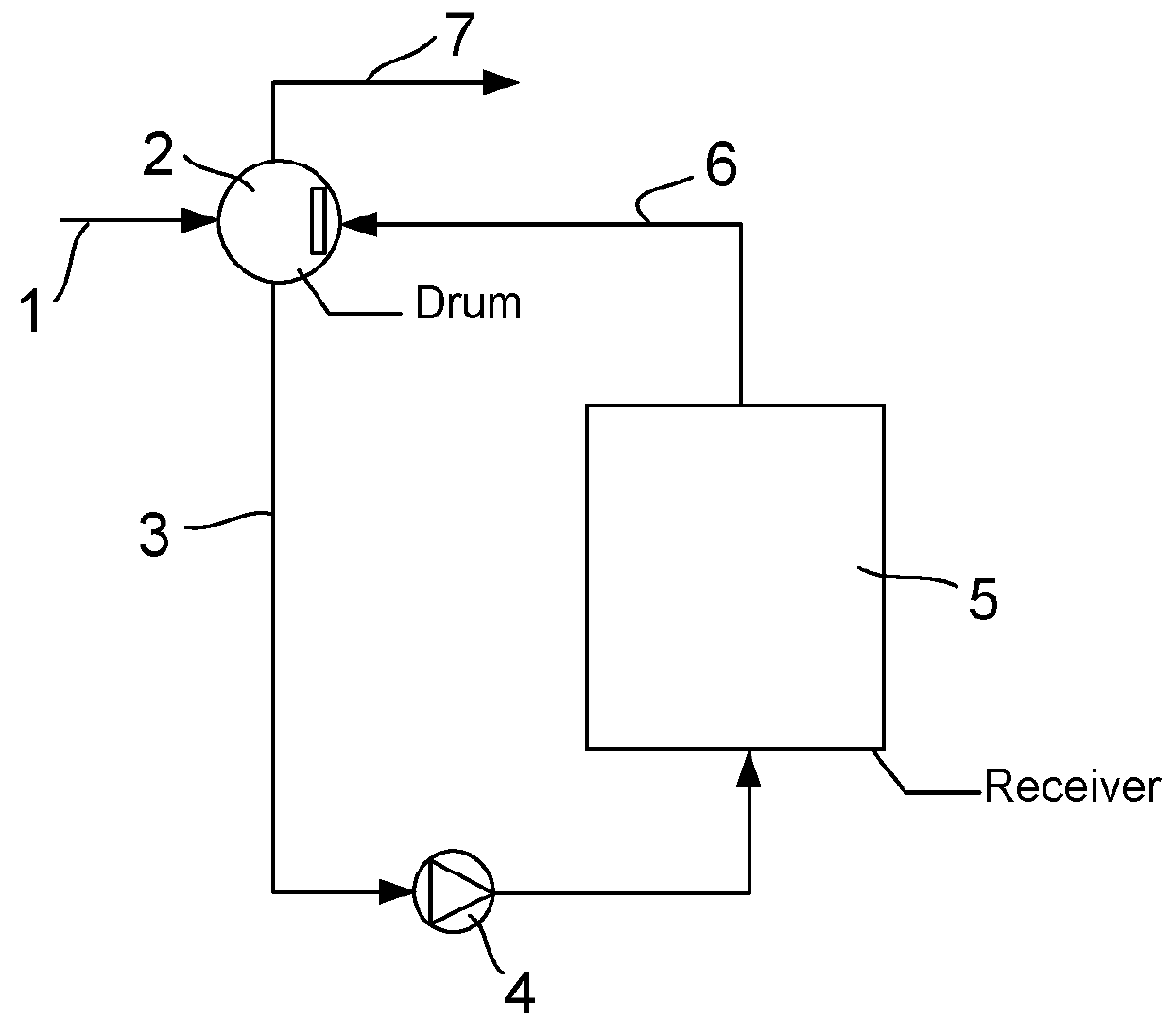
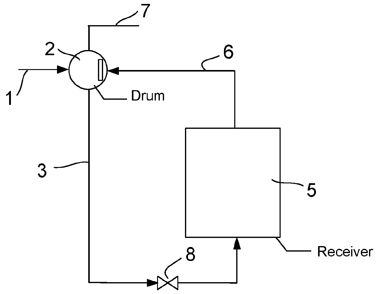
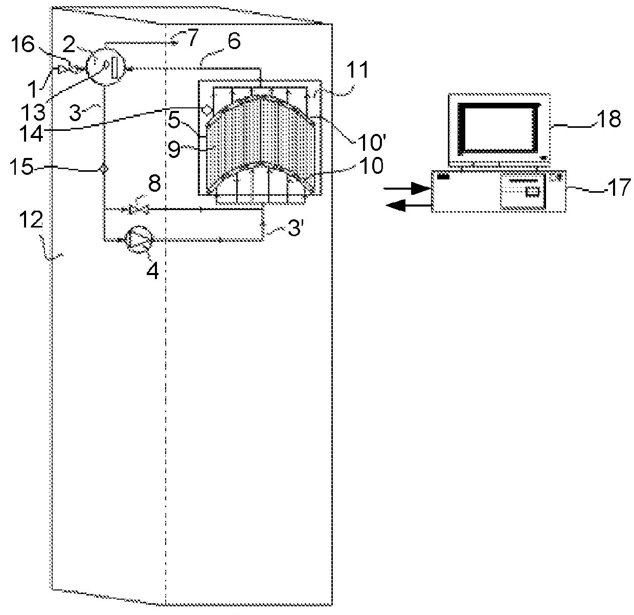
[0014]The design of a circuit that uses natural circulation for the supply of the working fluid to the receiver, allows more efficient use of solar energy since it

[0015]minimizes the pressure drops in the solar component, favoring the ascent without drive of the fluid through the receiver tubes and removing the need for forced recirculation of the same. The foregoing is presented as the main technological advantage of the proposed system compared to currently available devices.

[0016]The natural circulation is based on the physical fact that, by decreasing the density of a fluid, it tends to rise. So, if you have a hot focus, in a lower zone (receiver) and a cold focus in a higher zone (drum), natural circulation is achieved between the two foci, being able to eliminate the recirculation pumps. These pumps can be eliminated as long as the recirculation flow rate is sufficient to cool the receiver. The higher the cold focus is with respect to the hot, the recirculation flow rate obtai...


PUM


Abstract

The invention relates to a solar receiver with natural circulation for generating saturated steam, which uses water / steam as a heat-transfer fluid and includes a combined circuit for fluid recirculation (forced circulation and natural circulation). The system comprises: water-walls which receive the radiation on the surface thereof and inside which the working fluid changes phase; riser pipes through which the water / steam mix exiting the pipes of the receiver rises towards the drum; downpipes through which the recirculation water descends from the drum to the receiver; and a support pump in order to increase the incident power in the receiver and start up the plant when necessary.

Description

TECHNICAL FIELD OF THE INVENTION[0001]This invention pertains to the field of technologies for harnessing solar energy for electricity production, ranked among high concentration thermal solar systems, within the framework of the tower central receiver technologies with heliostats field.[0002]The invention describes both the design and the operating system of the receiver, which uses natural circulation as a method of supply of the working fluid to the system.BACKGROUND OF THE INVENTION[0003]Solar Concentration Systems (SCS) are used to increase the flux density of solar radiation so that the temperatures reached by the working fluid are those required for its use in industrial processes and in processes of power generation.[0004]Within the SCS there are the Tower Central Receiver Systems, where solar radiation is concentrated by using heliostats in a receiver located on top of a tower (in the focus of the optical system) and where it is transformed into thermal energy by the absorp...

Claims


Application Information

Patent Timeline
Patent Type & Authority Patents(United States)
IPC IPC(8): F24J2/44F24J2/04F24J2/24F24J2/07F24S10/70F24S20/20
CPCF24J2/44F24J2/07F24J2/248Y02E10/41Y02E10/44Y02E10/46F24S10/748F24S20/20F24S90/10Y02E10/50F02C1/05F02C6/00F03G6/06F24S50/80H01L31/04Y02E10/40
Inventor NAVIO GILABERTE, RA LSERRANO GALLAR, LUCIAOSUNA GONZALEZ-AGUILAR, RAFAELLLORENTE FOLCH, PAULAFERNANDEZ QUERO, VALERIO
Owner ABENGOA SOLAR NEW TECH SA
Why Eureka
Try Eureka