Radiation detector, and radiation imaging apparatus provided with detector

a radiation detector and detector technology, applied in the direction of instruments, patient positioning for diagnostics, applications, etc., can solve the problems of performance and production costs, unnecessary x-ray exposure of patients, and partial areas useless in data acquisition, so as to reduce the influence of dead zones of detectors on image quality, suppress radiation exposure, and reduce the effect of dead zones of detectors

Inactive Publication Date: 2016-07-12
TAKARA TELESYST
View PDF11 Cites 24 Cited by
  • Summary
  • Abstract
  • Description
  • Claims
  • Application Information

AI Technical Summary

Benefits of technology

[0026]In the radiation detector, such as an X-ray detector, configured with a mutually adjacent arrangement of plural modules, it is possible to greatly reduce influence of dead zones of the detector on image quality, while still suppressing an amount of radiation exposure. When this radiation detector is mounted on a radiation imaging apparatus, it is also possible to largely reduce influence of dead zones of the detector on image quality, suppress radiation exposure amount, and provide higher-resolution and finer images having an analog and natural appearance.

Problems solved by technology

As a result, in the scanned detection area, there is left partial areas which are not used for reconstructing an image, which partial areas are useless in terms of data acquisition.
In addition, acquisition from such partial areas provides a patient with unnecessary X-ray exposure.
This means that, in the photon counting type of detector, it is difficult to make each pixel smaller (down to a size of 150 μm or less) in structure as well as causing problems with performance and production cost, normally resulting in a pixel size of approx.
In other words, images reconstructed using data from the photon-counting type of detector are inferior in image resolution to those reconstructed using data from signal integration detectors whose pixels are approx.
That is, fineness of images is poorer.
Further, the former images are subjected to larger digital distortions, reducing accuracy in interpreting the images.

Method used


Image

  • Radiation detector, and radiation imaging apparatus provided with detector
  • Radiation detector, and radiation imaging apparatus provided with detector
  • Radiation detector, and radiation imaging apparatus provided with detector

Examples


first embodiment

[0055]Referring to FIGS. 1-17, a first embodiment of the radiation detector according to the present invention will now be described.

[0056]In the present embodiment, the radiation detector according to the present invention is an X-ray detector adopted by a dental X-ray panoramic imaging apparatus (hereinafter simply referred to as a panoramic imaging apparatus). Of course, as described later, this radiation detector can be mounted in a medical X-ray CT (Computed Tomography) scanner and an industrial X-ray CT apparatus. The X-ray detector in the present embodiment is exemplified as a photon counting type of X-ray detector. However, the radiation detector according to the present invention will not always be limited to the photon counting type, but may be applied to an integration type of detector which has the capability of detecting an intensity of incoming X-rays as an integrated amount calculated every designated period.

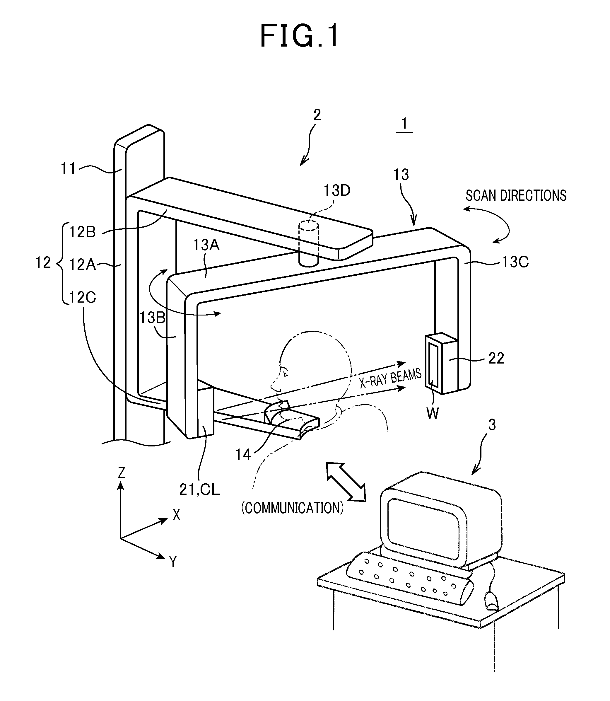
[0057]FIG. 1 outlines the panoramic imaging apparatus 1. Thi...

second embodiment

[0164]Referring to FIGS. 19 to 22, hereinafter is described a second embodiment of the radiation detector related to the present invention. In the present embodiment, the components identical with or similar to those in the first embodiment are given the same reference numerals for the sake of omitting or simplifying the description.

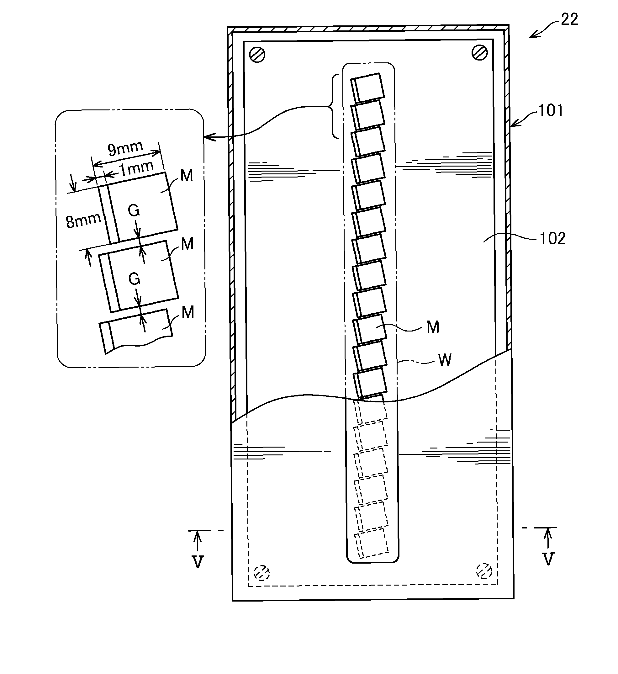
[0165]The present embodiment relates to an example in which the present invention is applied to an implemented X-ray CT (computed tomography) scanner. Since the configuration of the X-ray CT scanner is known, description is omitted. An X-ray detector 80 shown in FIG. 19 is applied to the X-ray CT scanner. Similar to the detector 22 described in the first embodiment, the detector 80 also includes a box-like housing 81 with a motherboard 82 being arranged inside. The housing 81 has an upper surface in which a rectangular X-ray incidence window W is formed. The motherboard 82 located right beneath the incidence window W has an upper surface in which a plura...


PUM


Abstract

An X-ray detector is provided with a plurality of modules each having a plurality of detection elements each composing a pixel, in which the detection elements convert incoming radiations to electric data depending on amounts of the radiations. The plural modules are mutually adjacently arranged on the same surface with a gap having a known width formed therebetween, such that the modules are arranged along at least one of a first X-axis and a first Y-axis, wherein the radiation detector is given a scan direction which is set along one of the first X- and Y-axes and the first Y-axis is perpendicular to the first X-axis. The plural detection elements of each module are two-dimensionally arranged along a second X-axis and a second Y-axis which are set obliquely to the first X-axis and the first Y-axis respectively and which are perpendicular to each other.

Description

CROSS-REFERENCE TO RELATED APPLICATIONS[0001]This application is a 371 U.S. National Stage of International Application No. PCT / JP2011 / 079530, filed Dec. 20, 2011, which claims priority to Japanese Patent Application No. 2010-284571, filed Dec. 21, 201. The disclosures of the above applications are entirely incorporated by reference herein.BACKGROUND OF THE INVENTION[0002]1. Field of the Invention[0003]The present invention relates to a radiation detector that detects quantities of radiation such as X-rays transmitted through an object being imaged and a radiation imaging apparatus provided with such a radiation detector to produce images of objects being imaged using data of the radiation detected by the detector, and in particular, to a radiation detector in which a plurality of direct conversion type of modules are arranged which have semiconductor layers to directly convert the radiation to electric signals corresponding in quantities to the radiation or a large-size radiation d...

Claims


Application Information

Patent Timeline
Patent Type & Authority Patents(United States)
IPC IPC(8): A61B6/00A61B6/14G01T1/17G01T1/29A61B6/04
CPCG01T1/2928G01T1/17A61B6/14A61B6/4233A61B6/0421A61B6/4435A61B6/4452A61B6/03G01T1/24G01T7/00
Inventor OGAWA, KOICHIYAMAKAWA, TSUTOMUHASHIMOTO, DAISUKENAGANO, TATSUYANAGAOKA, HIDEYUKITSUJITA, MASAHIRO
Owner TAKARA TELESYST
Why Eureka
Try Eureka