Control device for hybrid vehicle for controlling the hybrid vehicle when a collision is detected
a control device and hybrid technology, applied in the direction of automatic control systems, transportation and packaging, tractors, etc., can solve the problems of difficulty in speeding up the reduction of the voltage of the inverter circuit, and achieve the effect of preventing the generation of electromotive force by the rotation of the motor, increasing the rotational resistance of the motor, and speeding up the reduction of the rotation speed of the motor after the collision of the vehicl
- Summary
- Abstract
- Description
- Claims
- Application Information
AI Technical Summary
Benefits of technology
Problems solved by technology
Method used
Image
Examples
first embodiment
[0018]Hereinbelow, the invention will be described in detail with reference to the drawings. In the following embodiments, the drawings are appropriately simplified or modified, and dimensions and shapes of individual portions in the drawings are not necessarily precise.
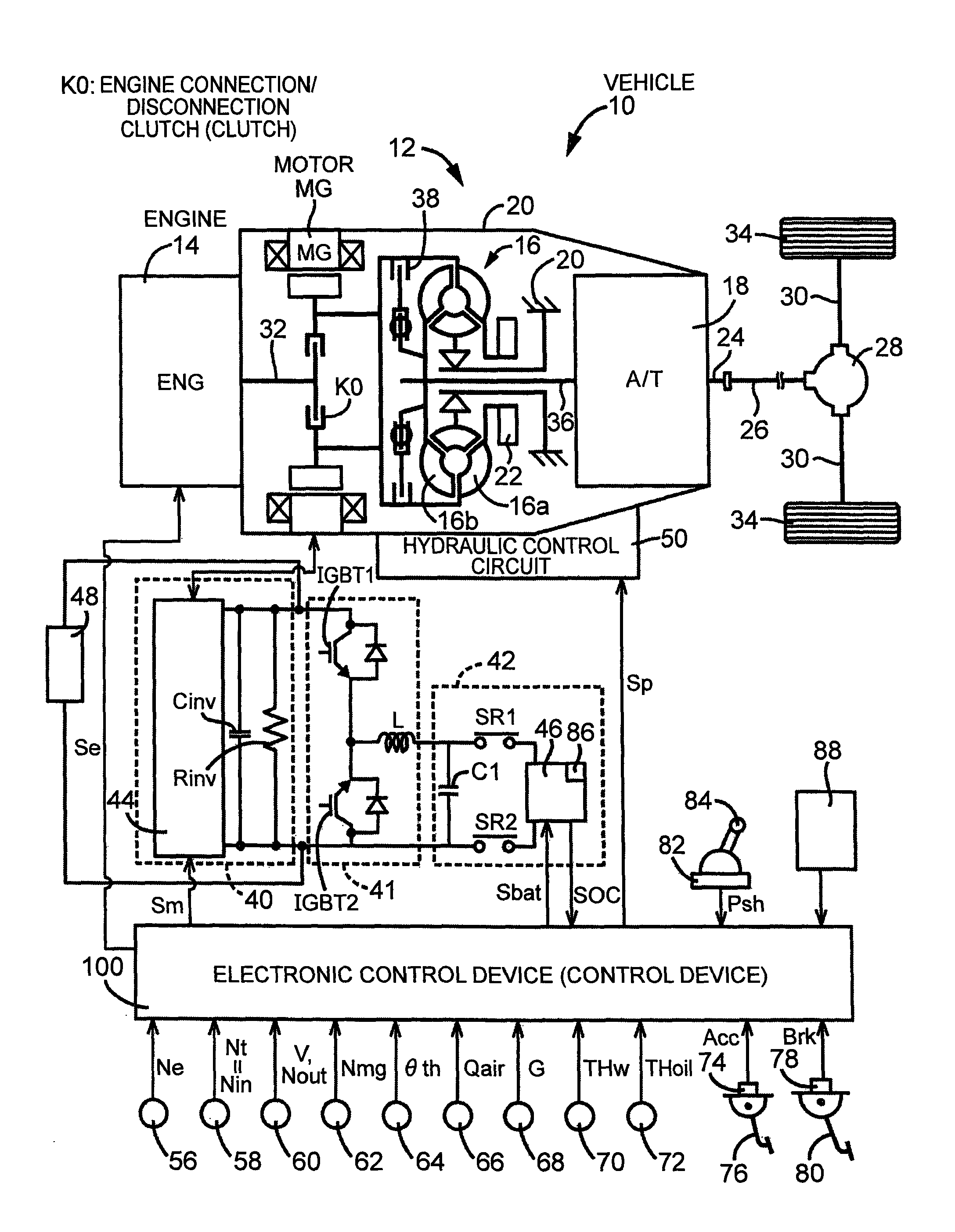
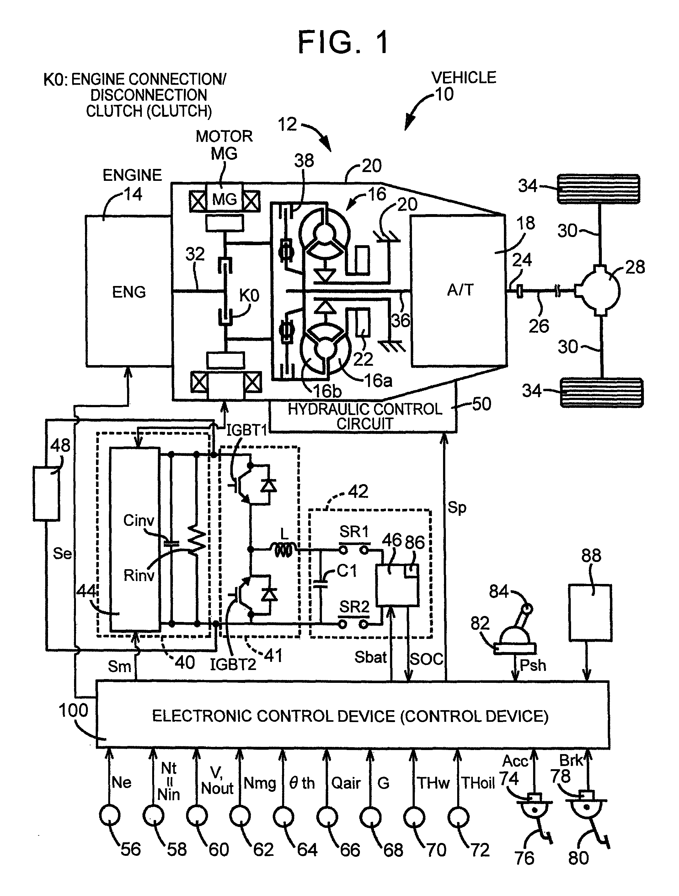
[0019]FIG. 1 is a view for explaining the schematic configuration of the power transmission path from an engine 14 to drive wheels 34 constituting a hybrid vehicle 10 (hereinafter referred to as a vehicle 10) to which the invention is preferably applied, and is also a view for explaining the principal portion of a control system provided in the vehicle 10 for an output control of the engine 14 functioning as a driving force source for running, a gear shift control of an automatic transmission 18, and a drive control of a motor MG.
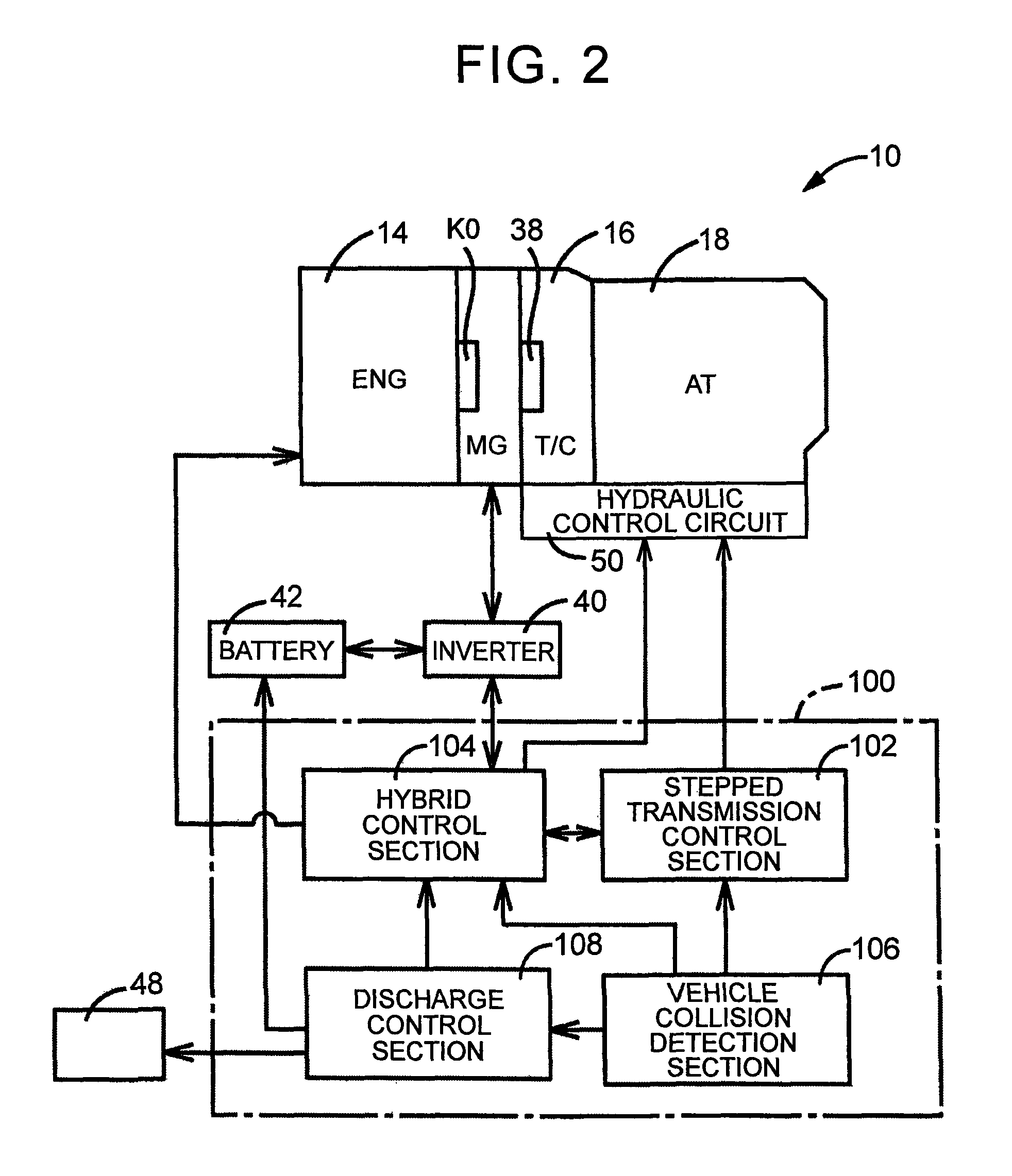
[0020]In FIG. 1, a vehicle power transmission device 12 (hereinafter referred to as a power transmission device 12) includes an engine connection / disconnection clutch K0, the motor MG, a tor...
second embodiment
[0048]Next, the invention will be described. Note that portions common to the above-described embodiment are designated by the same reference numerals and the description thereof will be omitted.
[0049]During the running of the vehicle 10, in a case where the vehicle 10 collides when the engine 14 is in a high load state or the engine rotation speed Ne is increasing, even when the fuel cut of the engine 14 is executed immediately after the vehicle collision, there are cases where the engine rotation speed Ne is not reduced, and the engine rotation speed Ne is increased due to inertia or maintained. In these cases, when the engine connection / disconnection clutch K0 is engaged, since the engine rotation speed Ne is high, the motor rotation speed Nmg is not reduced, the electromotive force is generated, and it takes time to discharge the inverter circuit 40 (the inverter capacitor Cinv). In such a case, similarly to the above-described embodiment, the electronic control device 100 perfo...
third embodiment
[0054]Next, the invention will be described. Note that portions common to the above-described embodiments are designated by the same reference numerals and the description thereof will be omitted. In a case where the vehicle speed V is a low vehicle speed when the vehicle 10 collides, the transmission input rotation speed Nin of the automatic transmission 18 is also a low rotation speed. In such a case, when the motor MG and the drive wheels 34 are connected to each other, the side of the drive wheels 34 functions as the rotational resistance of the motor MG, and the motor rotation speed Nmg is thereby reduced. Accordingly, in the case where the vehicle speed V is the low vehicle speed, the electronic control device 100 (the hybrid control section 104) controls the automatic transmission 18 functioning also as the connection / disconnection device that selectively establishes or interrupts the power transmission path between the engine 14 and the motor MG, and the drive wheels 34 to m...
PUM
 Abstract
Description
Claims
Application Information
 - R&D
- Intellectual Property
- Life Sciences
- Materials
- Tech Scout
- Unparalleled Data Quality
- Higher Quality Content
- 60% Fewer Hallucinations
Browse by: Latest US Patents, China's latest patents, Technical Efficacy Thesaurus, Application Domain, Technology Topic, Popular Technical Reports.
© 2025 PatSnap. All rights reserved.Legal|Privacy policy|Modern Slavery Act Transparency Statement|Sitemap|About US| Contact US: help@patsnap.com


