Variable frequency relaxation oscillator

Active Publication Date: 2016-07-26
NXP USA INC
View PDF8 Cites 9 Cited by
  • Summary
  • Abstract
  • Description
  • Claims
  • Application Information

AI Technical Summary

Problems solved by technology

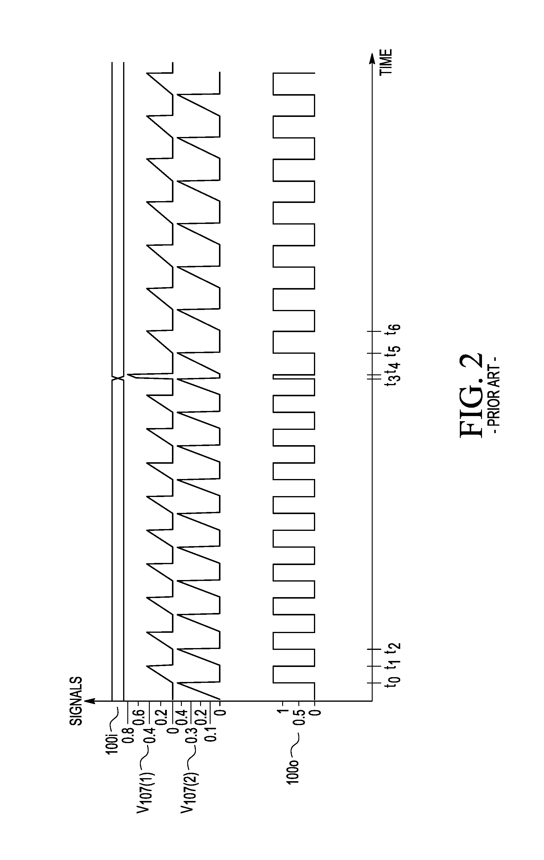
The glitch between time t3 and time t4 may adversely affect t

Method used


Image

  • Variable frequency relaxation oscillator
  • Variable frequency relaxation oscillator
  • Variable frequency relaxation oscillator

Examples


Embodiment Construction

[0019]Detailed illustrative embodiments of the present invention are disclosed herein. However, specific structural and functional details disclosed herein are merely representative for purposes of describing example embodiments of the present invention. Embodiments of the present invention may be embodied in many alternative forms and should not be construed as limited to only the embodiments set forth herein. Further, the terminology used herein is for the purpose of describing particular embodiments only and is not intended to be limiting of example embodiments of the invention.

[0020]As used herein, the singular forms “a,”“an,” and “the,” are intended to include the plural forms as well, unless the context clearly indicates otherwise. It further will be understood that the terms “comprises,”“comprising,”“has,”“having,”“includes,” and / or “including” specify the presence of stated features, steps, or components, but do not preclude the presence or addition of one or more other feat...


PUM


Abstract

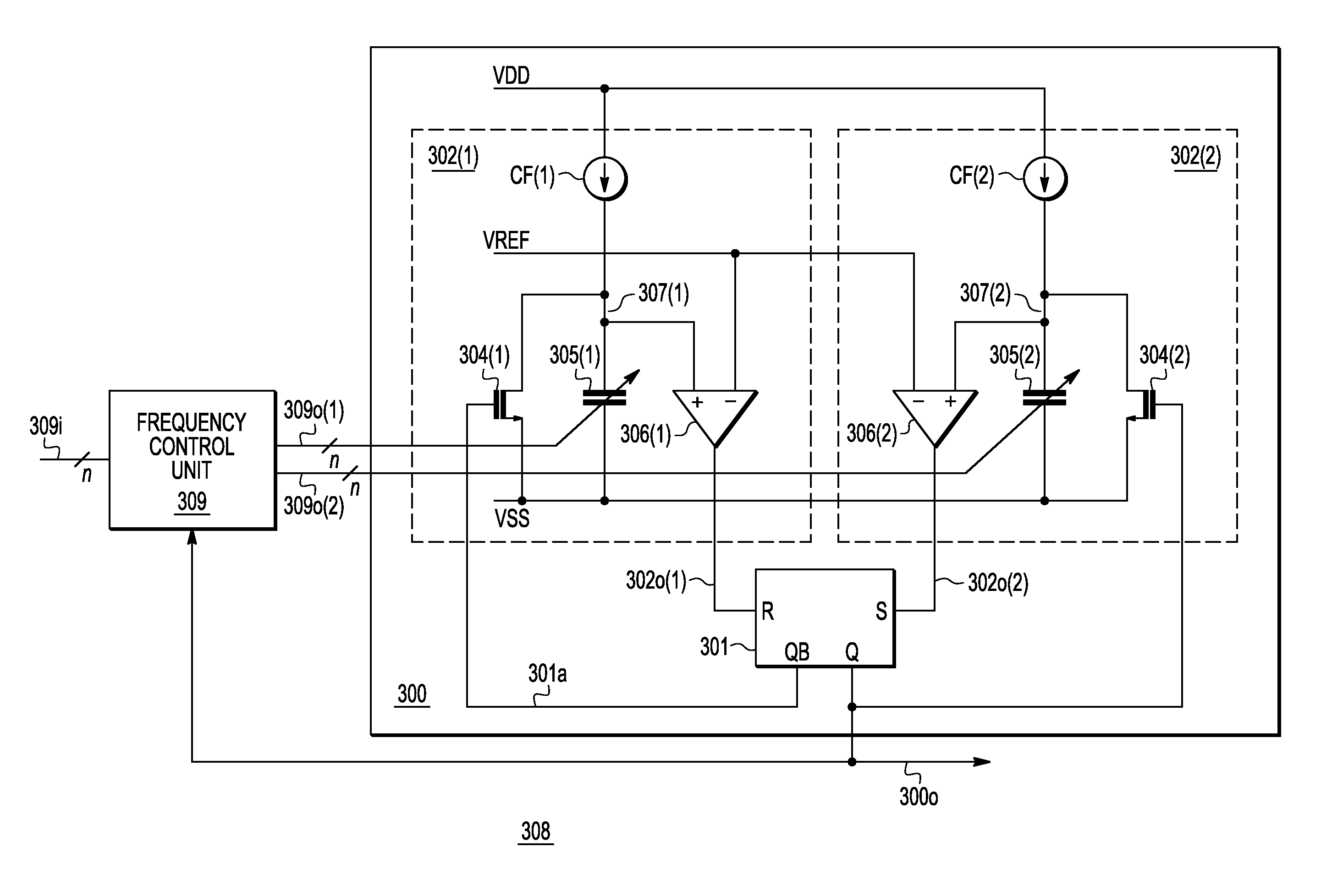
A relaxation oscillator system has a relaxation oscillator and a frequency control (FC) unit. The oscillator includes first and second oscillator sub-circuits and a latch. The first and second oscillator sub-circuits receive from the FC unit, respectively, first and second control signals for controlling corresponding outputs provided to the latch by the first and second oscillator sub-circuits. The latch outputs a variable frequency feedback signal provided to the FC unit. The FC unit receives a frequency control signal for controlling the frequency of an oscillator output signal and generates the first and second control inputs based on the frequency control signal and the feedback signal so that changes to the oscillator frequency are implemented by each oscillator sub-circuit while that sub-circuit is in an idle state to avoid glitches in the oscillator output signal.

Description

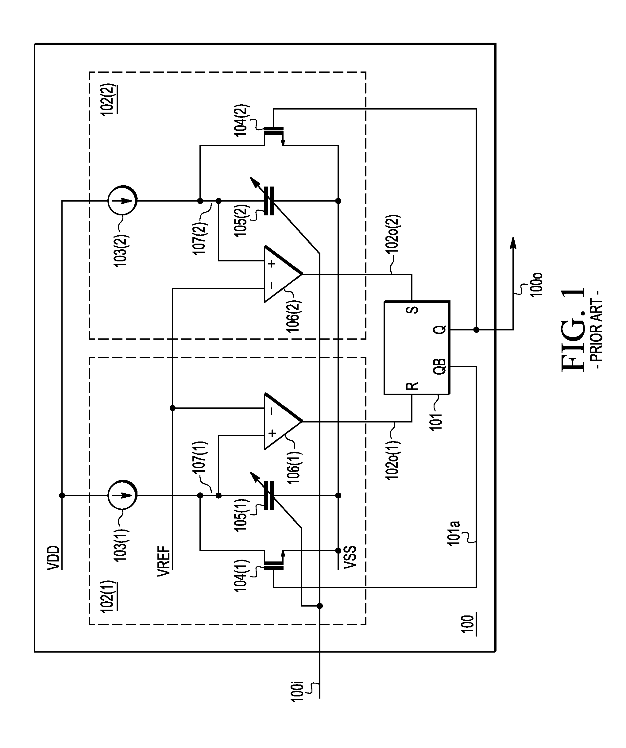
BACKGROUND OF THE INVENTION[0001]The present invention relates to integrated circuits (IC) and, more particularly, to a variable frequency relaxation oscillator.[0002]FIG. 1 is a simplified schematic circuit diagram of a conventional relaxation oscillator 100. The oscillator 100 receives a frequency control signal 100i, which determines an output oscillation frequency, and outputs an oscillation signal 100o, whose frequency depends on the received frequency control signal 100i and which may be used as a clock signal. The oscillator 100 has a set / reset (SR) latch 101 and two oscillator sub-circuits 102. The SR latch 101 has a set (S) input, a reset (R) input, a Q output, and a complementary QB output.[0003]Each oscillator sub-circuit 102 receives (i) the frequency control signal 100i, (ii) a drain supply voltage VDD, (iii) a source supply voltage VSS, and (iv) a reference voltage VREF. The oscillator 100 uses the two substantially identical oscillator sub-circuits 102, rather than ju...

Claims


Application Information

Patent Timeline
IPC IPC(8): H03K3/26H03K7/06H03L7/087H03K4/502H03K3/037H03L7/18H03K19/21H03K5/24H03K3/08H03K3/0231
CPCH03K7/06H03K3/037H03K4/502H03K5/24H03K19/21H03L7/18H03L7/087H03K3/0231H03K3/08
Inventor WANG, ZHENGXIANGLIANG, CHAOZHOU, JIAN
Owner NXP USA INC
Why Eureka
Try Eureka