Dynamic channel switching for wireless mesh networks

a wireless mesh network and dynamic channel technology, applied in the field of wireless mesh networks, can solve the problems of insufficient channel bandwidth, failure to propose interference limits, and detrimental to the capacity and quality of network system services, and achieve the effect of increasing the connectivity of nodes

Inactive Publication Date: 2016-07-26
TELEKOM MALAYSIA BERHAD
View PDF11 Cites 0 Cited by
  • Summary
  • Abstract
  • Description
  • Claims
  • Application Information

AI Technical Summary

Benefits of technology

[0017]It is an advantage of the present invention to provide a method of dynamic channel switching that is autonomous by way of introducing a switching metric in execution of the steps. The switching metric considers achievable data rate on the channel, size of frame to transmit, and latency of the channel switching as the factors that decide the channel switching.
[0018]It is another advantage of the present invention to provide a method of dynamic channel switching that increases connectivity of the node in the wireless mesh network beyond the number of physical nodes present therein which provides more rooms for optimization to a routing protocol.
[0019]It is yet another advantage of the present invention to provide a method of dynamic channel switching that enables each pair of interacting nodes to connect over the least loaded channel, and thus, utilizing the allocated frequency spectrum at the best.

Problems solved by technology

In the wireless mesh network which is interference-limited, the channel bandwidth is insufficient due to limited spectrum that is shared with numerous mesh links within the network.
Co-channel interference, in addition, that is caused by excessive power usage and bad frequency planning is detrimental to the network system capacity and quality of service.
The default protocol also fails to propose an interference limit beyond which the interference is detrimental to the network connection that requires channel switching.
However, the channel switching based on the interference only, at sometimes, is unnecessary and provides no improvements to the quality of service.
The prior art fails to anticipate the dynamic channel switching for the wireless mesh network that utilizes or quantifies factors other than the abovementioned factors that might essential for the switching.

Method used


Image

  • Dynamic channel switching for wireless mesh networks
  • Dynamic channel switching for wireless mesh networks
  • Dynamic channel switching for wireless mesh networks

Examples


Embodiment Construction

[0026]In the following description, for purposes of explanation, numerous details are set forth, such as flowcharts and system configurations, in order to provide an understanding of one or more embodiments of the present disclosure. However, it is and will be apparent to one skilled in the art that these specific details are not required in order to practice the present disclosure.

[0027]As used herein, a “wireless mesh network” may describe a communication network made up of nodes organized in a mesh topology that consists of mesh clients, mesh routers and gateways.

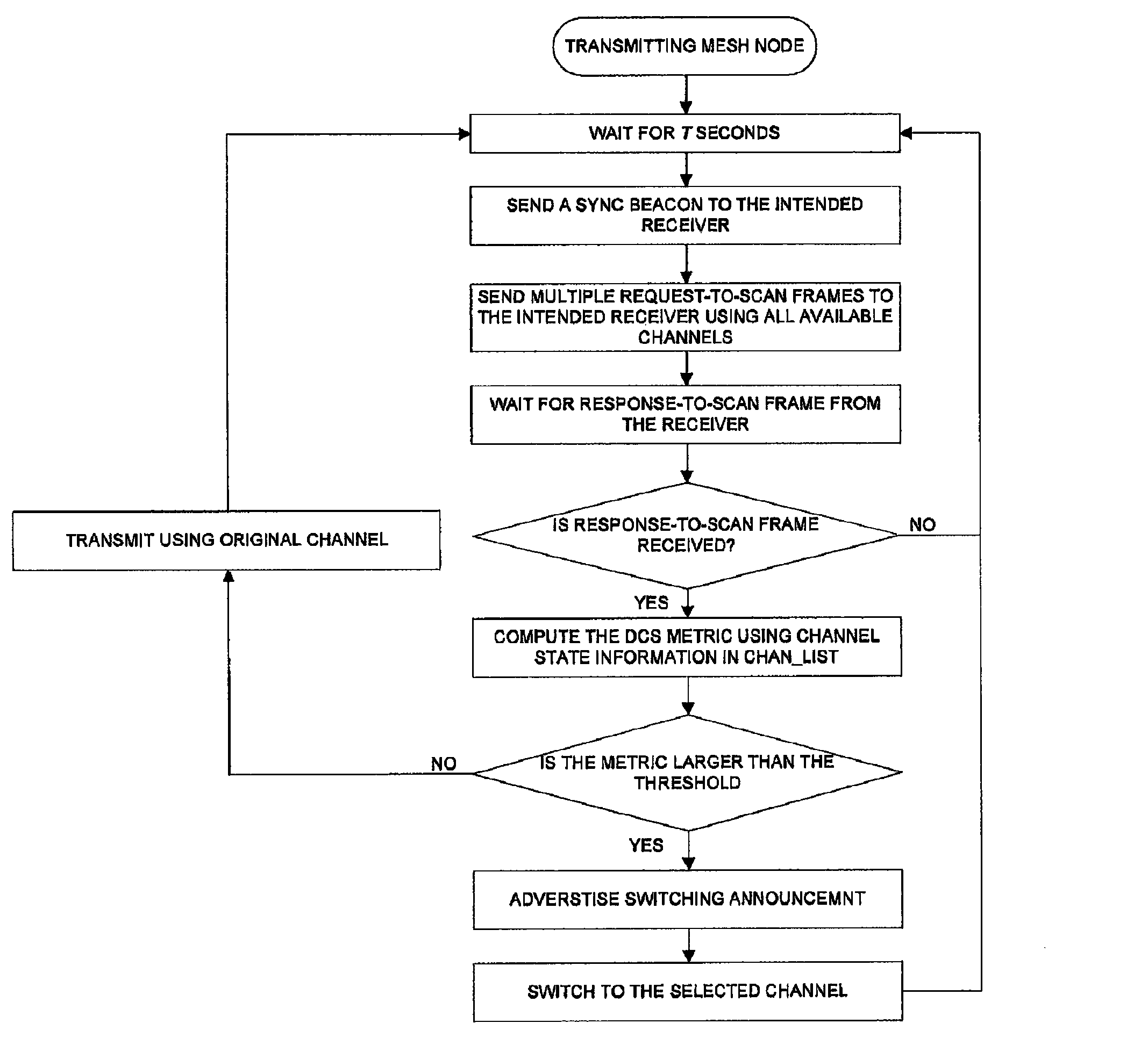
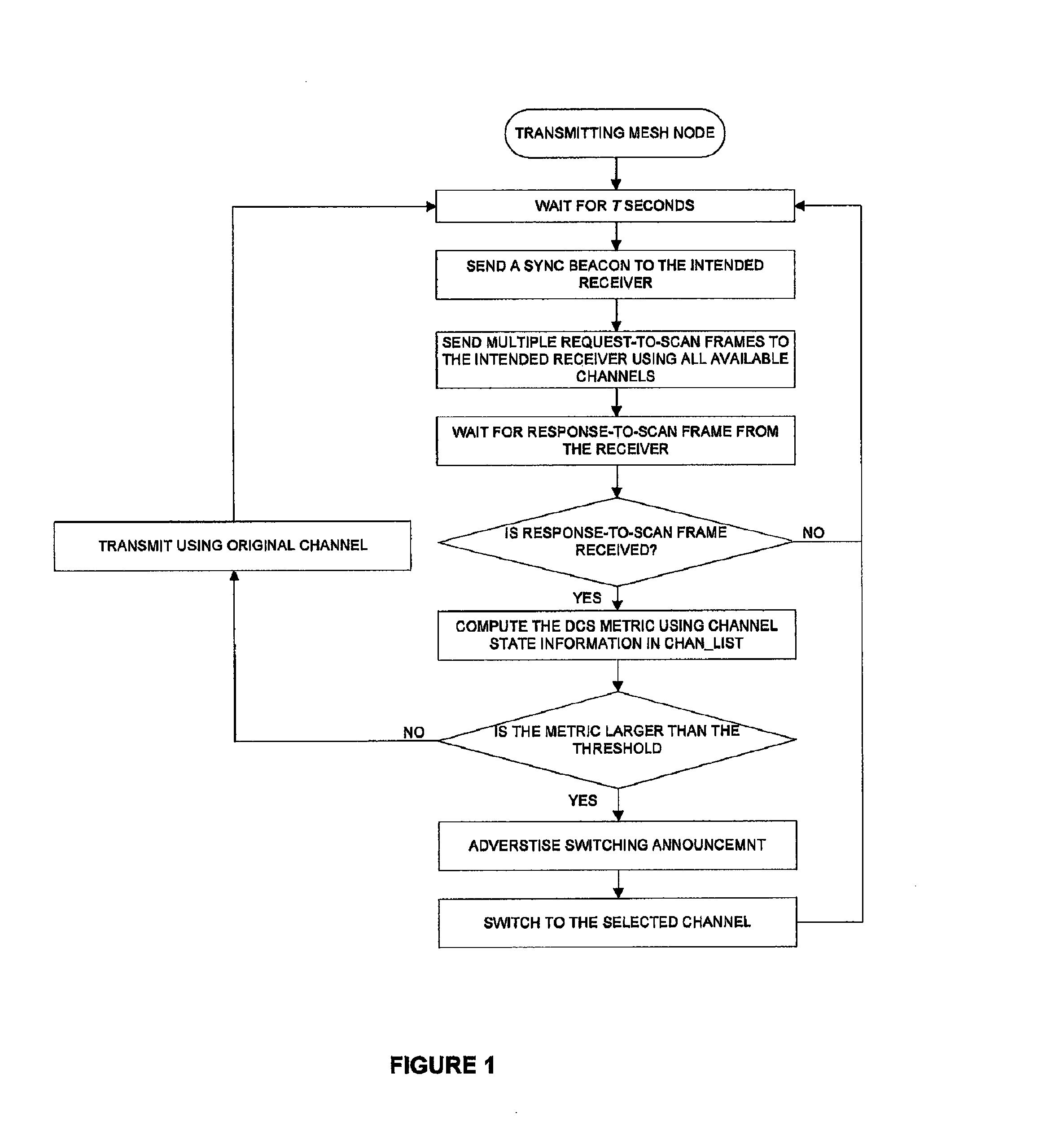
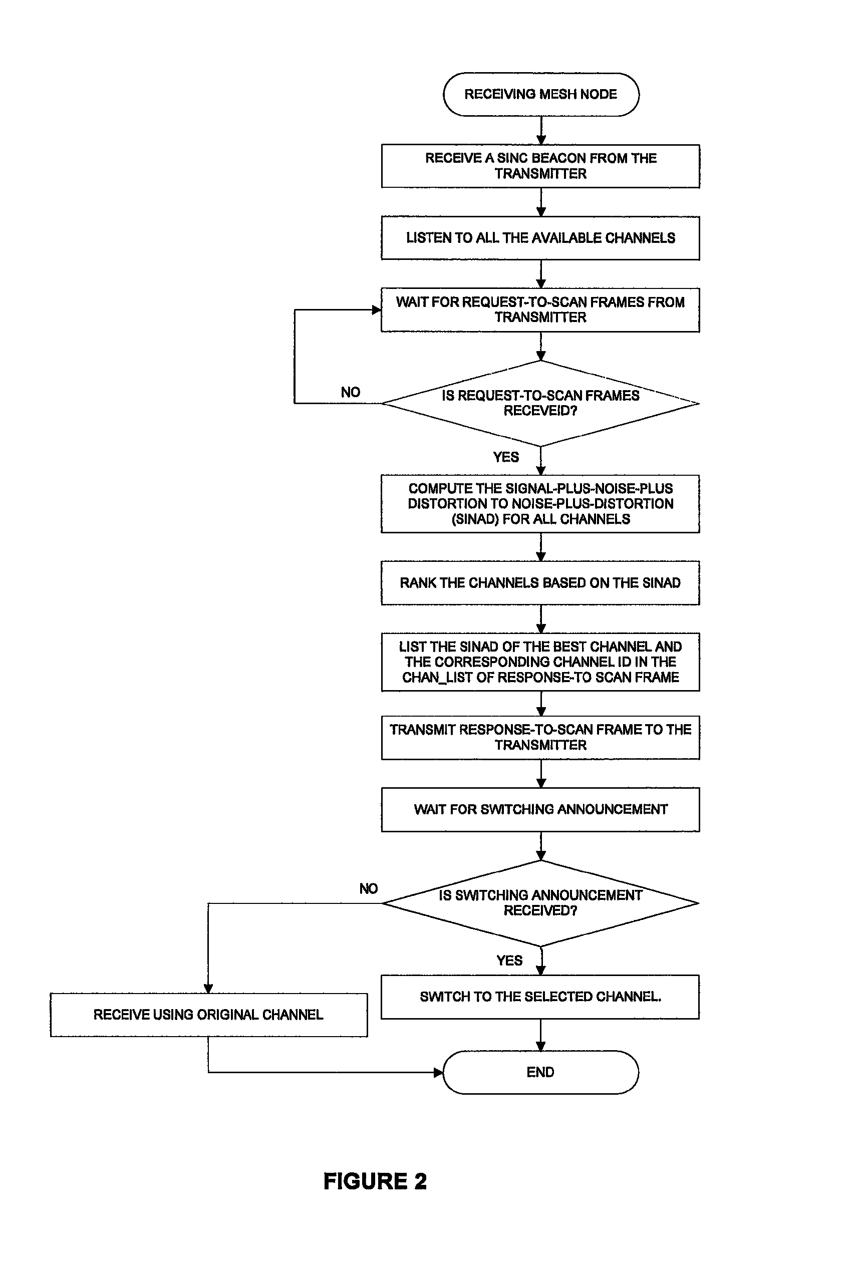
[0028]A “dynamic channel switching” may describe a dynamic assignment strategies that allow any nodes to be assigned any channel, and nodes can frequently switch from one channel to another, and thereby offering the potential to use many channels with few nodes.

[0029]A “node” or mesh node may describe two types of nodes: mesh routers and mesh clients. The mesh routers contain additional routing functions to support mesh ...


PUM


Abstract

The present invention relates to a method of dynamic channel switching in a wireless mesh network that is in conformance with an IEEE 802.11s standard. The method comprises the steps of transmitting a request frame to a node for scanning a channel associated with the node; determining a link quality of the channel; receiving a response frame from the node; and switching to the channel if the switching metric is larger than a switching threshold, wherein if otherwise, remain unswitched. The switching metric integrates the interference, transmission frame size, latency of channel switching and data rate of the node on the channel.

Description

BACKGROUND OF THE INVENTION[0001]1. Field of the Invention[0002]The present invention relates generally to wireless mesh networks. More particularly, the present invention relates to dynamic channel switching in a wireless mesh network that conforms to an IEEE 802.11s standard.[0003]2. Background Information[0004]Wireless mesh network is a communication network that made of radio nodes organized in a mesh topology. A typical wireless mesh network which aims to provide ubiquitous high bandwidth access for a large number of users often consists of mesh clients, mesh routers and gateways. The integration of the wireless mesh network with other networks such as the Internet, cellular, IEEE 802.11, IEEE 802.15, IEEE 802.16, sensor networks and many more can be accomplished through the gateways and bridging functions in the mesh routers.[0005]In recent years, the wireless mesh network together with related application and services have been actively researched. The wireless mesh network i...

Claims


Application Information

Patent Timeline
Patent Type & Authority Patents(United States)
IPC IPC(8): H04W36/24H04W72/08H04W36/00H04W24/00H04W40/24H04W40/12H04W84/12H04W36/30
CPCH04W36/0055H04W24/00H04W72/085H04W36/30H04W84/12H04W8/005H04W36/06H04W84/18H04W36/0085H04W72/542
Inventor LEE, CHIN KWANGTAN, CHEE KEONGYEOH, CHUN YEOWLIM, WEE KEONGBIN MOKHTAR, MOHAMMAD HARRIS
Owner TELEKOM MALAYSIA BERHAD
Why Eureka
Try Eureka