Laser ultrasound testing in limited-access areas

Active Publication Date: 2016-08-02
THE BOEING CO
View PDF26 Cites 5 Cited by
  • Summary
  • Abstract
  • Description
  • Claims
  • Application Information

AI Technical Summary

Benefits of technology

The patent describes an apparatus and method for inspecting a structure using a laser system and a mobile platform. The laser system generates a laser beam that is projected onto a surface of the structure using a projection system. The laser beam causes ultrasonic waves to form within the structure, which can be detected using an alignment system. The apparatus and method allow for precise and non-destructive inspection of structures, improving efficiency and accuracy in the inspection process.

Problems solved by technology

As one illustrative example, the bays formed by the spars of a horizontal stabilizer may be difficult to inspect.
However, these traditional ultrasound systems may be unable to handle variations in the shapes of the surfaces of these bays as well as desired.
For example, these traditional ultrasound systems may be unable to handle the non-precise radii of curvature as well as desired.
However, the size and / or weight of some currently available laser ultrasound testing systems may prevent these testing systems from being used in confined areas and / or other types of limited-access areas.
In some cases, the large robotic cell may be unable to move into and / or fit within certain areas.
Ensuring this type of protection may increase the expense of testing more than desired.
The increased expense may reduce the feasibility of using these types of testing systems at the production level, or manufacturing level, of a composite structure.
However, these types of testing systems may have a lower signal-to-noise ratio than desired.
Consequently, the data generated using these types of testing systems may be less accurate and / or reliable than desired.

Method used


Image

  • Laser ultrasound testing in limited-access areas
  • Laser ultrasound testing in limited-access areas
  • Laser ultrasound testing in limited-access areas

Examples


Embodiment Construction

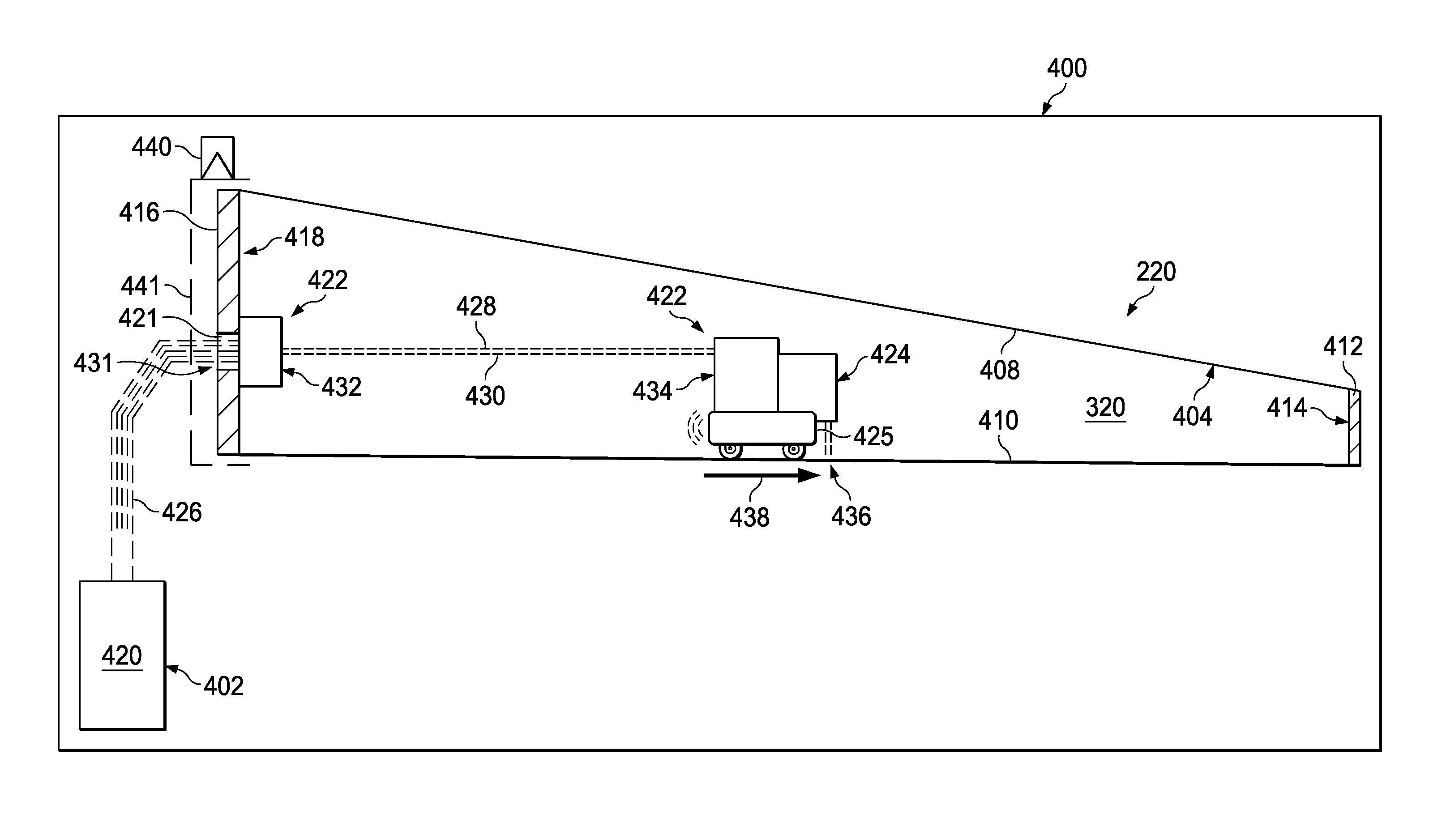
[0027]The different illustrative embodiments recognize and take into account different considerations. For example, the illustrative embodiments recognize and take into account that an articulated tube may be used to guide a laser beam generated by a laser ultrasound testing system to a location remote to the laser ultrasound testing system. The articulated tube may allow the laser beam to be emitted within otherwise hard to reach locations. In other words, the articulated tube may extend the reach of the laser ultrasound testing system.

[0028]However, the illustrative embodiments recognize and take into account that the length of the articulated tube and the joints of the tube may limit the areas into which the articulated tube may enter. Consequently, the illustrative embodiments recognize that it may be desirable to have a laser ultrasound testing system capable of inspecting regions of interest that are located in areas limited-access areas.

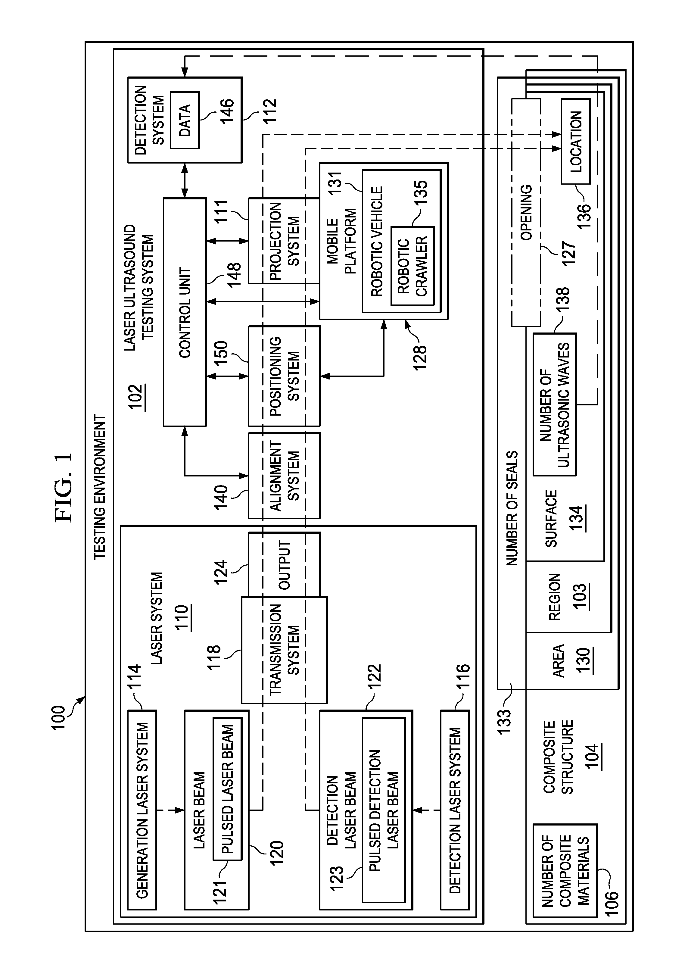
[0029]With reference now to FIG. 1, an ...


PUM


Abstract

A method and apparatus for inspecting a structure. In one illustrative embodiment, an apparatus comprises a laser system located outside of an area that includes a region of a structure to be inspected, a mobile platform located within the area to be inspected, and a projection system associated with the mobile platform. The laser system is configured to generate a laser beam. The projection system receives the laser beam and projects the laser beam onto a surface of the region of the structure. The laser beam causes a number of ultrasonic waves to form within the structure.

Description

BACKGROUND INFORMATION[0001]1. Field[0002]The present disclosure relates generally to laser ultrasound testing and, in particular, to the laser ultrasound testing of composite structures. Still more particularly, the present disclosure relates to an apparatus, system, and method for using laser ultrasound testing to inspect regions of interest in areas to which access is limited.[0003]2. Background[0004]A laser ultrasound testing (UT) system is a nondestructive testing (NDT) system that may be used to test structures, such as composite structures, for undesired inconsistencies. A nondestructive testing system may also be referred to as a nondestructive inspection (NDI) system or a nondestructive evaluation (NDE) system.[0005]Typically, a laser ultrasound testing system uses a laser beam to induce ultrasound within a composite structure. The laser beam may be a pulsed laser beam. The laser beam may be directed towards a location on a surface of a composite structure. When the laser b...

Claims


Application Information

Patent Timeline
IPC IPC(8): G01N29/34G01N29/26G01N29/24G01N29/22G01N29/265
CPCG01N29/225G01N29/2418G01N29/265G01N2291/0231G01N2291/2694
Inventor GEORGESON, GARY ERNESTSTEWART, ALAN FRANKMOTZER, WILLIAM P.BRADY, STEVEN KENNETHBOSSI, RICHARD H.GORDON, III, CLARENCE LAVERE
Owner THE BOEING CO
Why Eureka
Try Eureka