Modular submergible breakwater for lowering water wave kinetic energy especially during storms or rough waters

a technology of submerged breakwaters and modules, applied in marine site engineering, construction, groynes, etc., to achieve the effect of removing any barrier to navigation, and lowering the kinetic energy of water waves

Inactive Publication Date: 2016-08-09
INNOVATION & DEV
View PDF43 Cites 2 Cited by
  • Summary
  • Abstract
  • Description
  • Claims
  • Application Information

AI Technical Summary

Benefits of technology

[0024]The present invention relates to submergible modular breakwaters for lowering the kinetic energy of water waves. In particular, the present invention is directed toward a physical embodiment that, when in its floating position, will provide resistance to the movement of water waves in the direction of the waves for a large range of wave periods. The invention is a submergible modular breakwater that can be kept underwater on the sea or lake floor as not to provide any barrier to navigation until it is needed to lower the kinetic energy of waves, when it is quickly raised afloat to provide protection, especially for coastal erosion control during storms or rough waters. Once the lowering of the kinetic energy of water waves is not longer needed, the modular breakwater can be quickly sunk to the sea or lake floor in order to remove any barrier to navigation.
[0025]It is the main objective of the present invention to reduce the kinetic energy of water waves that reach the coastline, especially during storms or rough waters independently of the wave periods or heights.
[0026]It is another objective of the present invention to quickly and cheaply be raised from the sea or lake floor or be deployed from the coast to act as a breakwater before waves derived from storms or rough waters states arrive to the coastline.

Problems solved by technology

Recently, partly due to changes influenced by climate change such as sea raise and stronger storms, there have been major catastrophes in coastal areas in the world both in industrialized temperate weather countries and in non-industrialized tropical countries.
During storms, the principal damages caused by water waves are erosion, especially by the removal of sand in sandy beaches, destruction of infrastructure close to the coastline, and flooding.
Strong storms or rough waters in coastal areas have both direct and indirect economic and financial negative impacts.
Hurricane Irene arrived during the late summer of 2011 and caused more than $15 billion in property damage.
One of the indirect negative economic impacts, especially in coastal zones of tourist states like for example Florida and New Jersey, are reduction of tourism activities along after the passing of the storm.
In the case of tropical countries, especially small island countries, climate change derived destruction, through sea raise and stronger storms, will heavily impact the economy of such countries.
The projected sea-level rise will increase the vulnerability of that infrastructure, especially during extreme events.
Due to the concentration of population in these areas, damage to important infrastructure may be disruptive to economic, social and cultural activities.
As a direct result, many insurance and reinsurance companies withdrew from the market.
In 1995 Hurricanes Luis and Marilyn devastated coastal areas, causing severe damage to hotel and other tourism properties and leading to a 17% decrease in the number of tourist arrivals and adversely affecting employment and foreign exchange.
The 1998 hurricane season was especially devastating to Jamaica with long lasting effects resulting from hurricanes Georges and Mitch.
Sea level rise will combine a number of factors resulting in accelerated coastal erosion, increased flood risk and in some areas permanent loss of land.
. . Tropical Storm Iris damaged the west coast road and cut road access between Soufriere and Scotts Head.
Hurricane Luis damaged coastal structures—hotels, roads, utilities, jetties and fish landing sites.
There was severe damage to the beaches, especially on the west coast.
The road was washed out and the hotel damaged at Coconut Beach, similar damage occurred at Mero.
Fixed breakwaters, generally constructed with rocks, can be expensive to build especially when the water depth is more than 5 meters.
Additional disadvantages of this type of breakwater, beside costs, are affectation of the beach view, and the accumulation of sand between the breakwater and the coastline.
Revision of previous art indicates that this type of breakwaters can be impractical due to the following characteristics:a) They protrude from the water all the time, creating a possible navigating hazard;b) They are difficult to place on the water.
To attach a breakwater to the bottom may require piling, making the deployment very costly; andc) Water wave kinetic forces during storms could easily destroy this type of breakwater, due to the forces exert in the base of the pilings.
Prior Art floating breakwaters, have other disadvantages:a) They do not extend like a wall through the entire water column; therefore protection in the horizontal plane is not complete;b) They stay afloat all the time, creating possible navigating hazards;c) Due to the linear and / or cylindrical shape and the small diameter of the main components of such devices, a large number of units must be deployed in order to block the horizontal movement of water waves;d) Even though Stokes Law movement of the water molecules keeps pushing these floating devices towards the coast, the circular or elliptical movement of the molecules during the passing of waves also makes these devices move in a circular or elliptical manner.
This movement makes the barrier less efficient in stopping kinetic energy movement toward the coast due to the horizontal back-and-forth movement of the devices;e) Although some of these devices are designed in such a manner as to create more resistance to the movement of water waves and to reduce the back and forth movement when the water waves pass though then, for example by placing plates or components a half-wavelength distance from each other, these type of designs are impractical to deploy and costly to build due to size (i.e., minimum a half wavelength); andf) In many cases, these floating breakwaters are composed of many cylindrical units which are independently anchored and, since the diameter of each unit cannot be that large, a lot of anchors are required, as well as time to place them, in order to have an effective horizontal water movement blockage.

Method used


Image

  • Modular submergible breakwater for lowering water wave kinetic energy especially during storms or rough waters
  • Modular submergible breakwater for lowering water wave kinetic energy especially during storms or rough waters
  • Modular submergible breakwater for lowering water wave kinetic energy especially during storms or rough waters

Examples


first embodiment

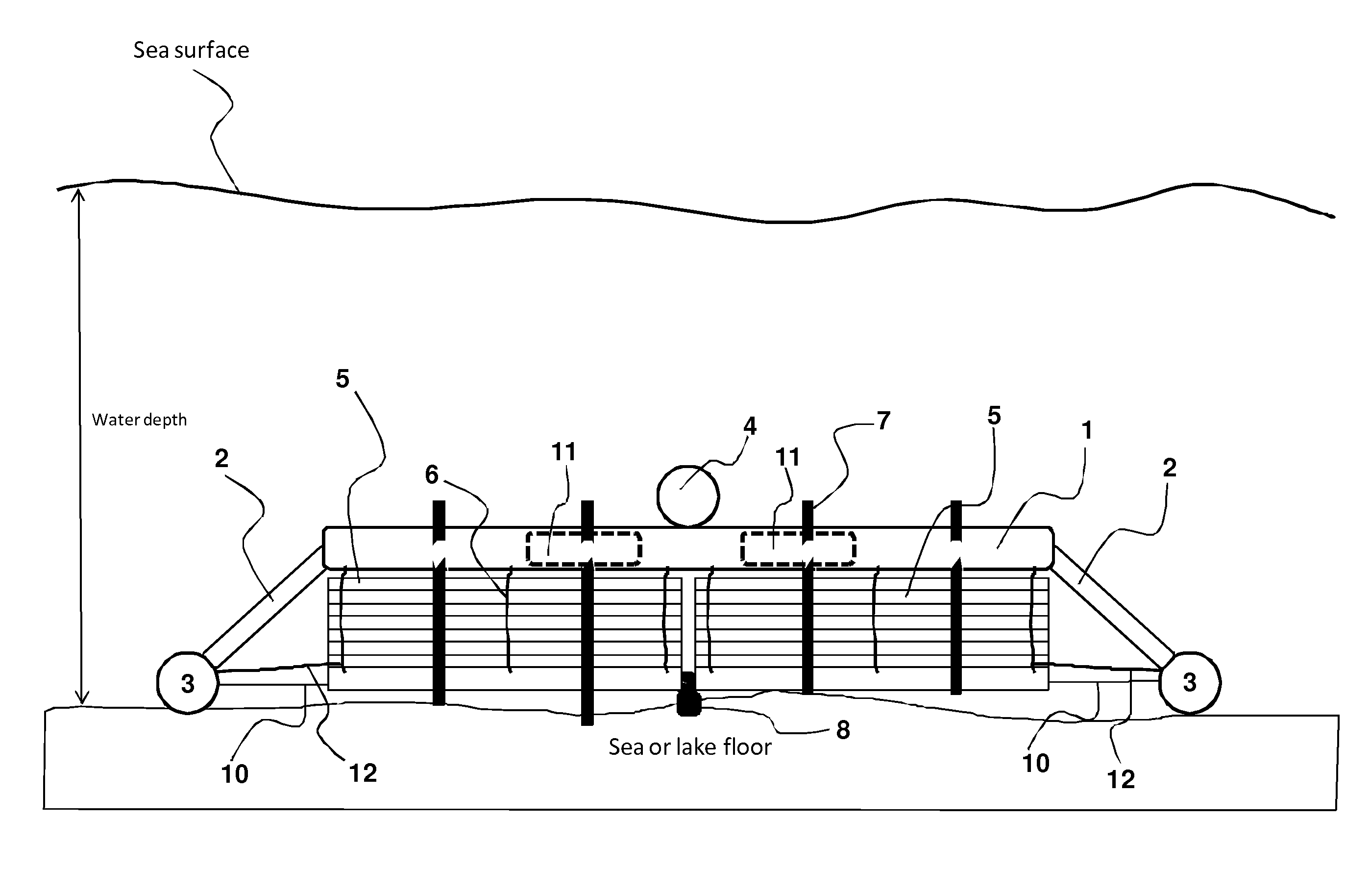
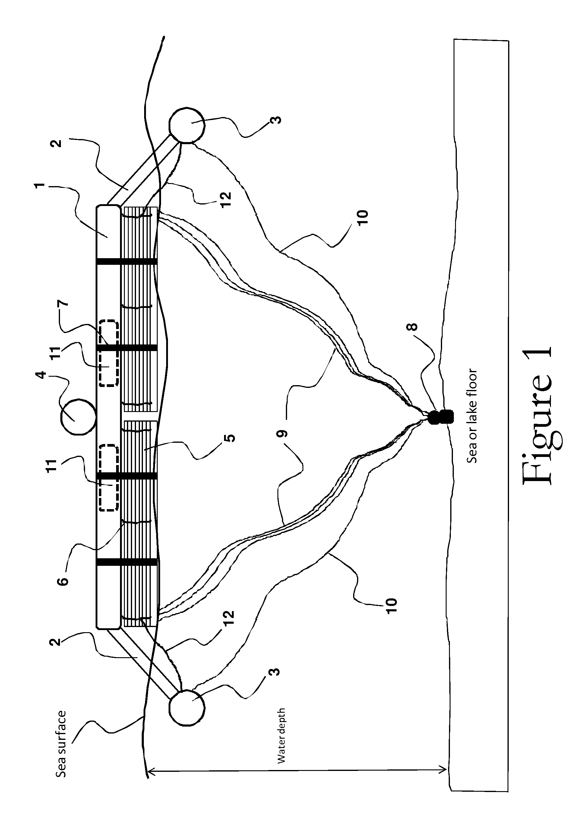
[0072]FIGS. 3 and 4 show general side views of the modular breakwater of the present invention in the floating position with the breakwater Venetian-like slats in the raised position. In FIG. 3, the breakwater device is floating over the wave crest and the anchor lines 9 and 10 are in a taut stage. In FIG. 4, the breakwater device is floating over the wave trough and the anchor lines 9 and 10 are in a slack stage. Notice the different shape of the main float 3 and stabilizing float 4. Main floats 3 are designed to make the breakwater float in a catamaran manner and they can be design in any shape that can accomplish that purpose. The stabilizing float 4 can also be designed in any shape as to accomplish the purpose of stabilizing the breakwater (i.e., keeping the main frame 1 in horizontal position when sinking it to or raising it from the seafloor). By filling main float 3 with seawater first, and then float 4, through a system that is described in connection with FIGS. 8 and 9, th...

second embodiment

[0082]FIG. 16 is a general front view of the modular breakwater of the present invention in the floating position with the breakwater Venetian-like slats 5 in the raised position where the raising or lowering of the slats is performed by a mechanism 17. In this embodiment, the breakwater device will always be afloat, so there is no need for an air filling system described in FIGS. 8 and 9, nor the need for a stabilizing float 4. Main floats 3 may not need the holes 3a in the lowest position.

[0083]FIG. 17 is a general front view of the second embodiment of the modular breakwater of the present invention in the floating position with the breakwater Venetian-like slats 5 in the lowered position where the raising or lowering of the slats is performed by a mechanism 17.

third embodiment

[0084]FIG. 18 is a general front view of the modular breakwater of the present invention in the floating position with the breakwater Venetian-like slats 5 in the raised position, without any slats raising or lowering mechanism 17. In this embodiment, the breakwater device will always be afloat, so there is no need for an air filling system described in FIGS. 8 and 9, nor the need for a stabilizing float 4. Main floats 3 may not need the holes 3a in the lowest position. The Venetian-like slats 5 are shown in their raised position with ropes, belts or equivalent elements 7.

[0085]FIG. 19 is a general front view of the third embodiment of the modular breakwater of the present invention in the floating position with the breakwater Venetian-like slats 5 in the lowered position. Notice that, once the ropes, belts or equivalent elements 7 are cut or removed, the Venetian-like slats 5 fall into their lowered position due to the force of gravity.


PUM


Abstract

The present invention relates to submergible modular breakwaters for lowering the kinetic energy of water waves. In particular, the present invention is directed toward a physical embodiment that, when in its floating position, will provide resistance to the movement of water waves in the direction of the waves for a large range of wave periods. The invention is a submergible modular breakwater that can be kept underwater on the sea or lake floor as not to provide any barrier to navigation until it is needed to lower the kinetic energy of waves, when it is quickly raised afloat to provide protection, especially for coastal erosion control during storms or rough waters. Once the lowering of the kinetic energy of water waves is not longer needed, the modular breakwater can be quickly sunk to the sea or lake floor in order to remove any barrier to navigation.

Description

CROSS-REFERENCE TO RELATED APPLICATIONS[0001]The present application claims priority from Provisional U.S. Patent Application No. 61 / 953,209 filed on Mar. 14, 2014, and incorporated herein by reference.FIELD OF THE INVENTION[0002]The present invention relates to submergible modular breakwaters for lowering the kinetic energy of water waves. In particular, the present invention is directed toward a physical embodiment that, when in its floating position, will provide resistance to the movement of water waves in the direction of the waves for a large range of wave periods.BACKGROUND OF THE INVENTION[0003]Recently, partly due to changes influenced by climate change such as sea raise and stronger storms, there have been major catastrophes in coastal areas in the world both in industrialized temperate weather countries and in non-industrialized tropical countries. An example of a catastrophe in an industrialized temperate weather country was the one caused by Hurricane Sandy in the East ...

Claims


Application Information

Patent Timeline
Patent Type & Authority Patents(United States)
IPC IPC(8): E02B3/06
CPCE02B3/062
Inventor ATILANO, ALVAROBLANCO, VICTORRODRIGUEZ, JOSERODRIGUEZ DOTTI, LEONELLA
Owner INNOVATION & DEV
Why Eureka
Try Eureka