
Method and apparatus to plan motion path of robot

a robot and motion path technology, applied in the direction of process and machine control, electrical programme control, instruments, etc., can solve the problems of wasting considerable time and unable to obtain solutions, and achieve the effect of reducing the probability of local minima occurring, and reducing the time consumed to search for optimal motion paths

Active Publication Date: 2016-08-09
SAMSUNG ELECTRONICS CO LTD
View PDF21 Cites 13 Cited by
  • Summary
  • Abstract
  • Description
  • Claims
  • Application Information

AI Technical Summary

Benefits of technology

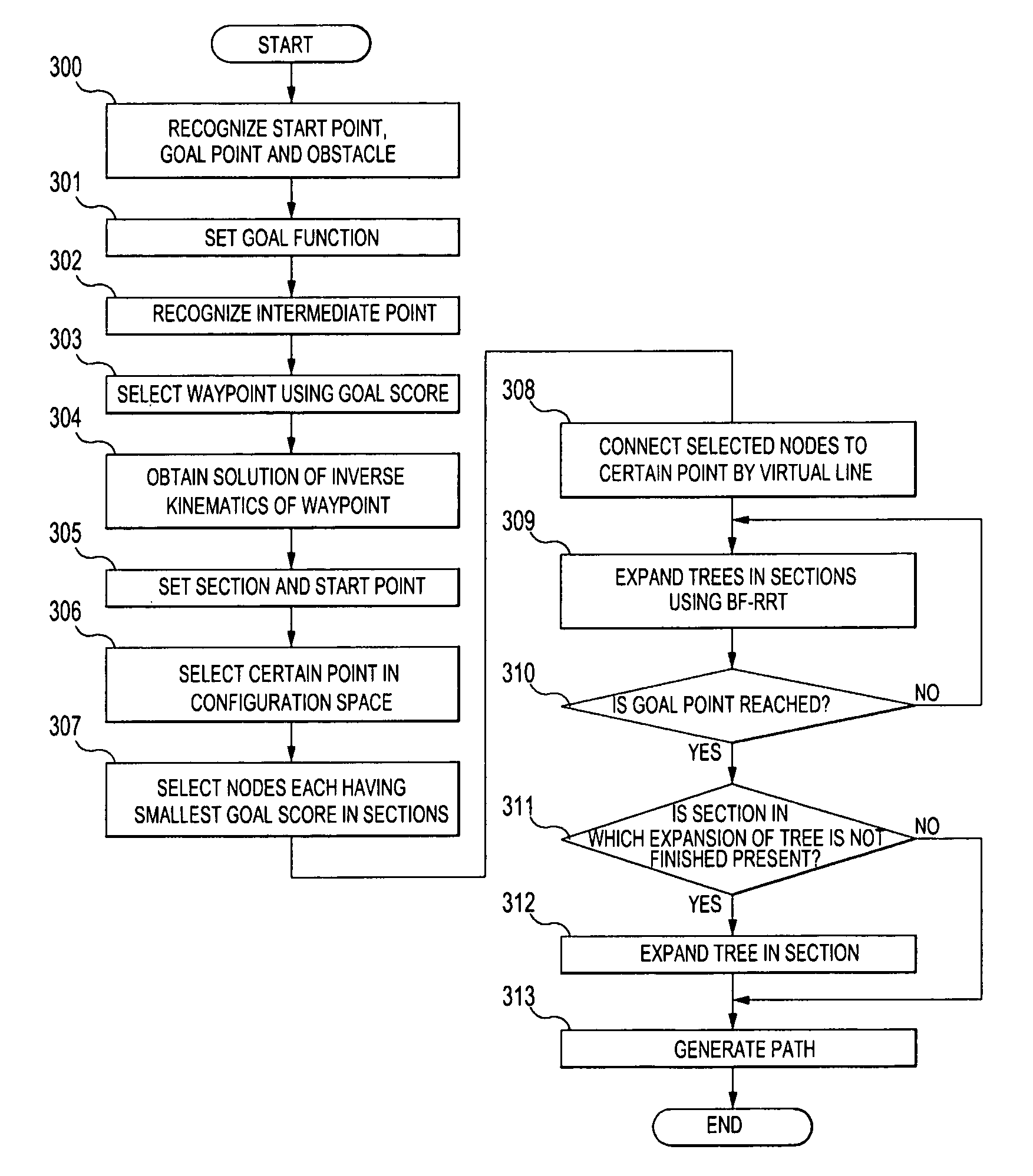
The invention provides a method and apparatus to plan a motion path for a robot that reduces the time needed to expand a tree, minimizes errors in the path plan, and improves performance. The method involves selecting a suitable waypoint based on a goal score, dividing the path into sections, and simultaneously expanding trees in the sections using a BF-RRT algorithm. This reduces the likelihood of local minima and allows for faster convergence to a solution. The method also decreases the number of samples discarded and improves the overall performance of the path plan.

Problems solved by technology

Early robots included manipulators used for automated or unmanned tasks of manufacturing plants or industrial robots such as transportation robots, and performed dangerous tasks, simply repeated tasks or tasks using large force in place of a human.
However, in the RRT algorithm of the related art, if a goal function is not accurately determined when the closest node is selected so as to expand the tree reaching the goal point, local minima occur and thus a solution may not be obtained.
In addition, it takes considerable time to expand the tree.

Method used


Image

  • Method and apparatus to plan motion path of robot
  • Method and apparatus to plan motion path of robot
  • Method and apparatus to plan motion path of robot

Examples


Embodiment Construction

[0040]Reference will now be made in detail to the at least one embodiment, examples of which are illustrated in the accompanying drawings, wherein like reference numerals refer to like elements throughout.

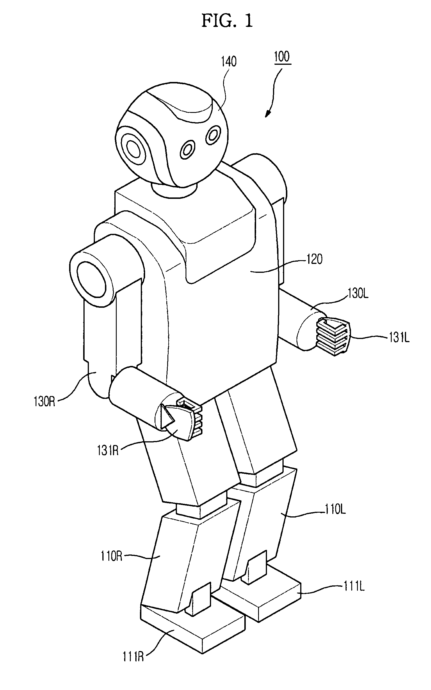
[0041]FIG. 1 is an appearance view showing an example of a robot according to an embodiment.

[0042]In FIG. 1, the robot 100 according to the embodiment is a bipedal robot which walks erect using two legs 110R and 110L similar to a human, and includes a trunk 120, two arms 130R and 130L and a head 140 mounted on an upper side of the trunk 120, and feet 111R and 111L and hands 131R and 131L respectively mounted on the front ends of the two legs 110R and 110L and the arms 130R and 130L. In reference numerals, R and L denote right and left, respectively.

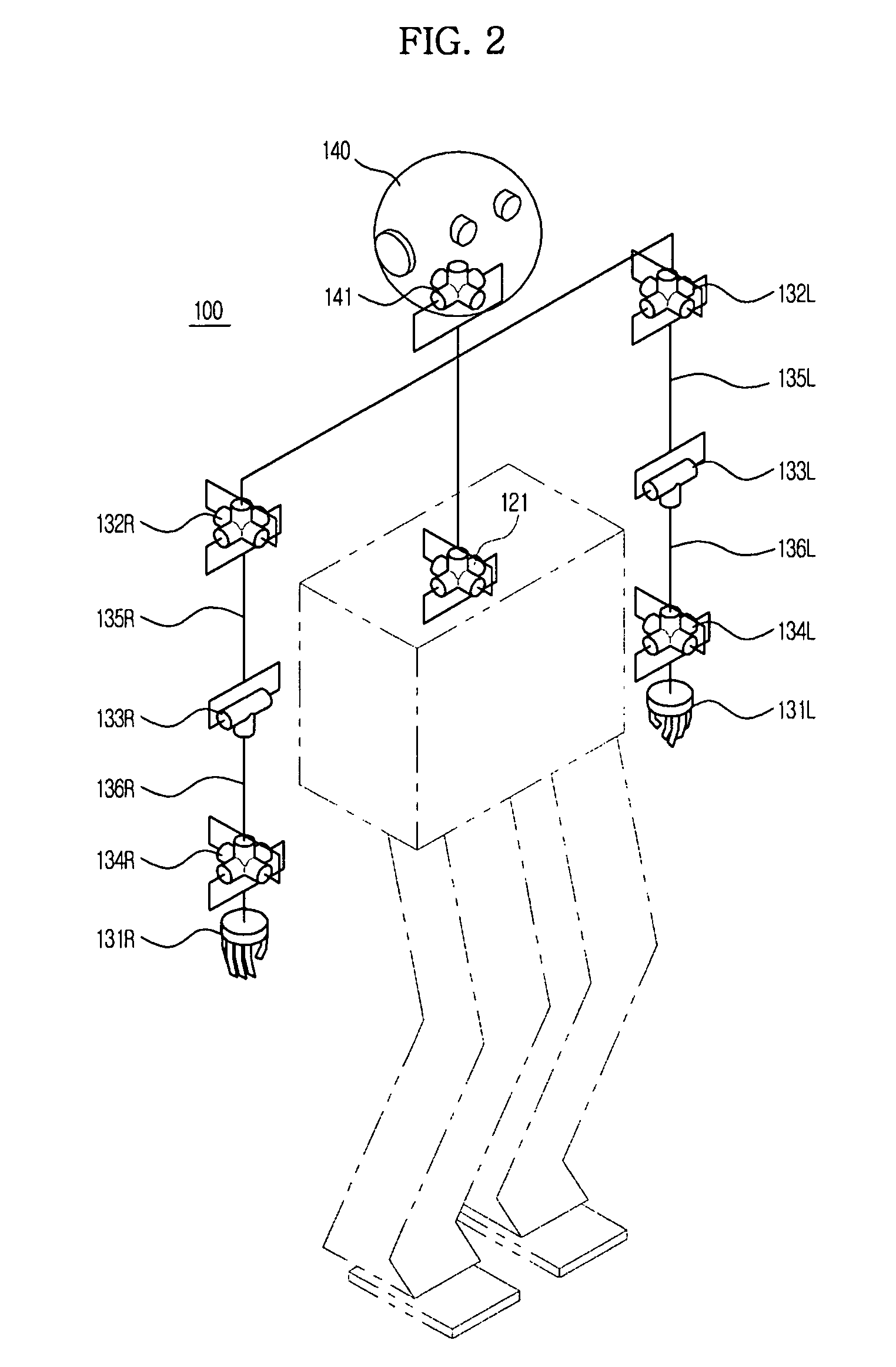
[0043]FIG. 2 is a view showing the structure of the main joints of the robot shown in FIG. 1.

[0044]In FIG. 2, the two arms 130R and 130L respectively include shoulder joints 132R and 132L, elbow joints 133R and 133L and wrist joints 134R...


PUM


Abstract

A suitable waypoint is selected using a goal score, a section from a start point to a goal point through the waypoint is divided into a plurality of sections based on the waypoint with a solution of inverse kinematics, and trees are simultaneously expanded in the sections using a Best First Search & Rapidly Random Tree (BF-RRT) algorithm so as to generate a path. By this configuration, a probability of local minima occurring is decreased compared with the case where the waypoint is randomly selected. In addition, since the trees are simultaneously expanded in the sections each having the waypoint with a solution of inverse kinematics, the solution may be rapidly obtained. A time consumed to search for an optimal motion path may be shortened and path plan performance may be improved.

Description

CROSS-REFERENCE TO RELATED APPLICATIONS[0001]This application claims the benefit of Korean Patent Application No. 2009-0073257, filed on Aug. 10, 2009 in the Korean Intellectual Property Office, the disclosure of which is incorporated herein by reference.BACKGROUND[0002]1. Field[0003]Embodiments relate to a method and apparatus to plan a motion path of a robot, which is not obstructed by an obstacle in a working environment.[0004]2. Description of the Related Art[0005]In general, a mechanical device which performs motions similar to human motion using an electrical or magnetic mechanism is called a robot. Early robots included manipulators used for automated or unmanned tasks of manufacturing plants or industrial robots such as transportation robots, and performed dangerous tasks, simply repeated tasks or tasks using large force in place of a human. Recently, research into a humanoid robot which has joints similar to those of a human, coexists with a human in a working and living sp...

Claims


Application Information

Patent Timeline
Patent Type & Authority Patents(United States)
IPC IPC(8): G05B19/04G05D1/02B25J9/16G06F19/00G05B19/18G06F17/10
CPCB25J9/1666G05D1/0217G05D1/0274G05D2201/0216G05D2201/0217G05B2219/40476G05B2219/40264B25J9/10B25J11/00B25J13/08
Inventor KIM, MYUNG HEEROH, KYUNG SHIKLIM, SANLIM, BOK MANCHUNXU, GUO
Owner SAMSUNG ELECTRONICS CO LTD
Learn More