
Method for calibrating a counting digital X-ray detector, X-ray system for performing such a method and method for acquiring an X-ray image

a digital x-ray detector and counting technology, applied in the field of counting digital x-ray detector calibration, can solve the problems of detectors with adjustable threshold values of discriminators, inability to continue counting without error, and noise of threshold values, and achieve the effect of high image quality

Active Publication Date: 2016-08-16
SIEMENS HEALTHCARE GMBH
View PDF6 Cites 7 Cited by
  • Summary
  • Abstract
  • Description
  • Claims
  • Application Information

AI Technical Summary

Benefits of technology

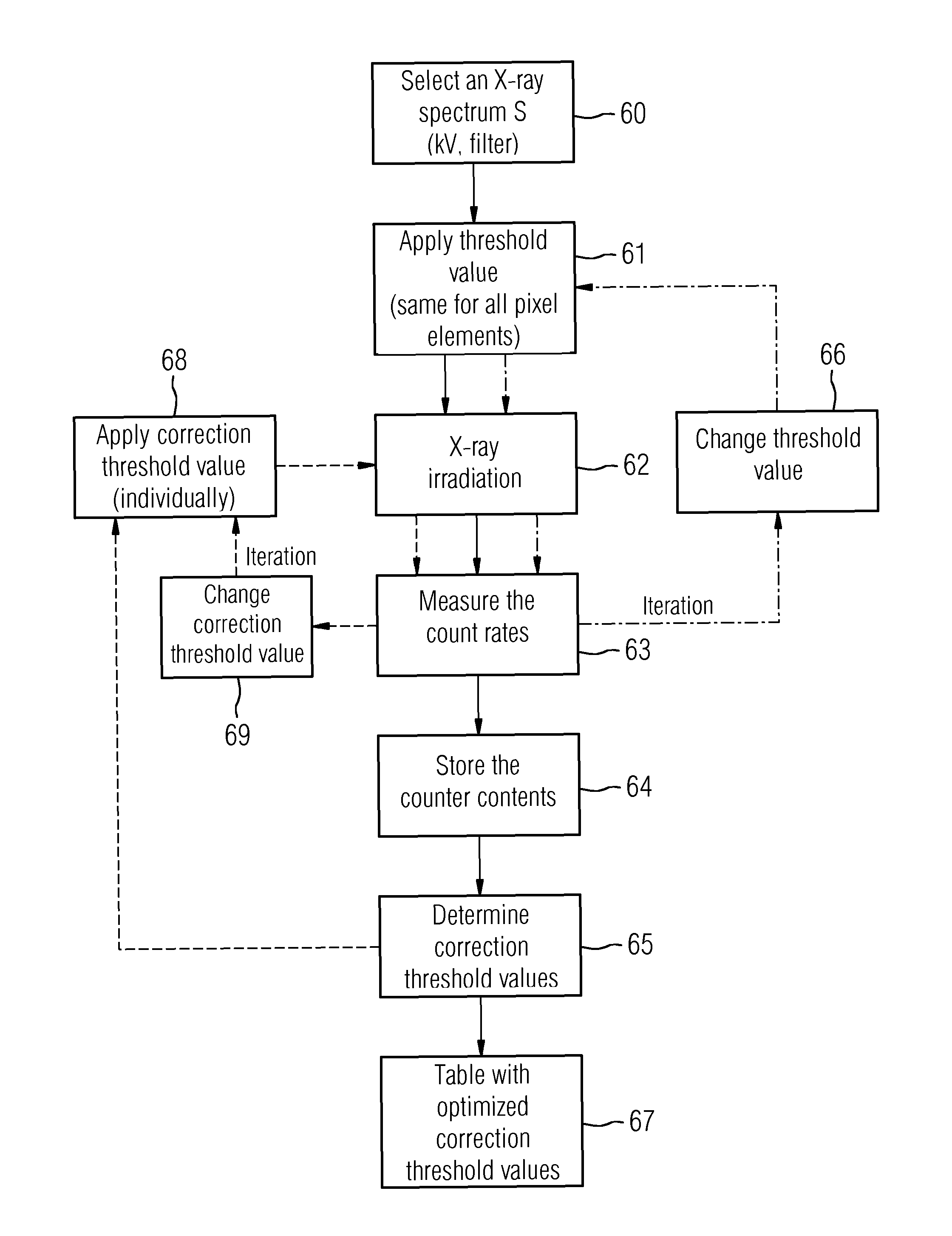
The present invention provides a method for measuring the count rate of pixel elements in an X-ray detector and using these measurements to determine individual correction threshold values for each pixel element. These correction threshold values are then used to improve image quality and reduce threshold-value-induced noise in X-ray imaging. The method is robust and can be performed with any X-ray source, making it easy to automate and quickly recalibrate. The method also involves fitting and smoothing characteristic curves, calculating average values, and generating characteristic lines for different X-ray spectra to determine the correction threshold values for each pixel element. Overall, this method allows for a more comprehensive and accurate calibration of X-ray detectors, resulting in high-quality X-ray images.

Problems solved by technology

This readout process requires a certain amount of time during which it is not possible to continue counting without error.
Counting detectors with adjustable discriminator threshold values exhibit problems such as the following.
However, since only X-ray quanta having X-ray energy that lies above the threshold values are counted, different portions of the energy spectrum are counted, resulting in “threshold value noise”.
Such effects may lead to structural or “fixed pattern”-like noise.

Method used


Image

  • Method for calibrating a counting digital X-ray detector, X-ray system for performing such a method and method for acquiring an X-ray image
  • Method for calibrating a counting digital X-ray detector, X-ray system for performing such a method and method for acquiring an X-ray image
  • Method for calibrating a counting digital X-ray detector, X-ray system for performing such a method and method for acquiring an X-ray image

Examples


Embodiment Construction

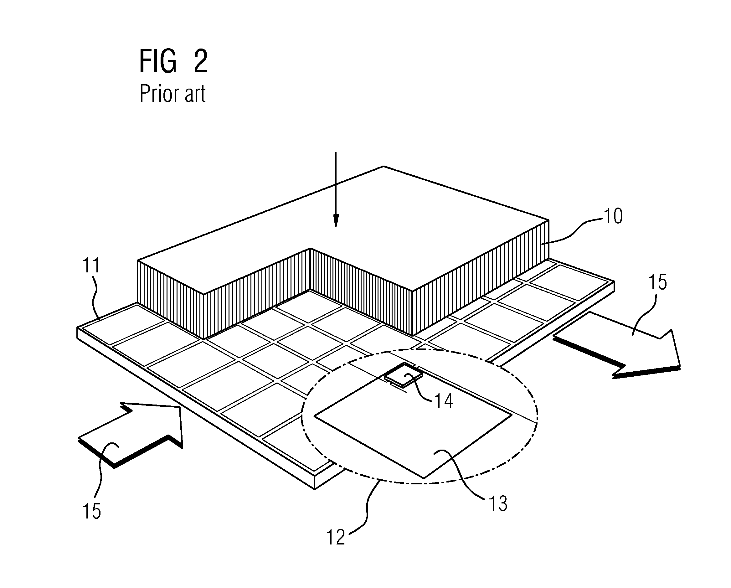
[0048]The present embodiments describe a method for calibrating a digital counting X-ray detector, by which a threshold value noise may be reduced or completely avoided. As a result, the quality of the X-ray imaging is significantly improved. An X-ray detector that may be calibrated by a method of the type has, for example, a structure such as described with reference to FIG. 3, including a direct converter 24 (e.g., CdTe or CZT) for converting X-ray quanta into electrical signals and a plurality of pixel elements in a matrix structure. The plurality of pixel elements may receive and register the signals as count events as a function of position provided the signals lie above a threshold value. The individual pixel elements have central functional elements, as shown, for example, in FIG. 5 (simply discriminating) or FIG. 7 (energy-discriminating). The threshold value that may be applied to the respective pixel element is adjustable.

[0049]Discriminators and analog-to-digital converte...


PUM


Abstract

A method for calibrating a counting digital X-ray detector includes performing a threshold value scan in at least one defined X-ray spectrum for irradiating the X-ray detector, which includes a matrix composed of pixel elements, storing count rates of the pixel elements as a function of respective applied threshold values, and from results of a measurement of count rates of the pixel elements, determining or calculating individual correction threshold values for the individual pixel elements. The individual correction threshold values correct a threshold value that is to be applied to the pixel elements for the defined X-ray spectrum such that threshold value noise is reduced.

Description

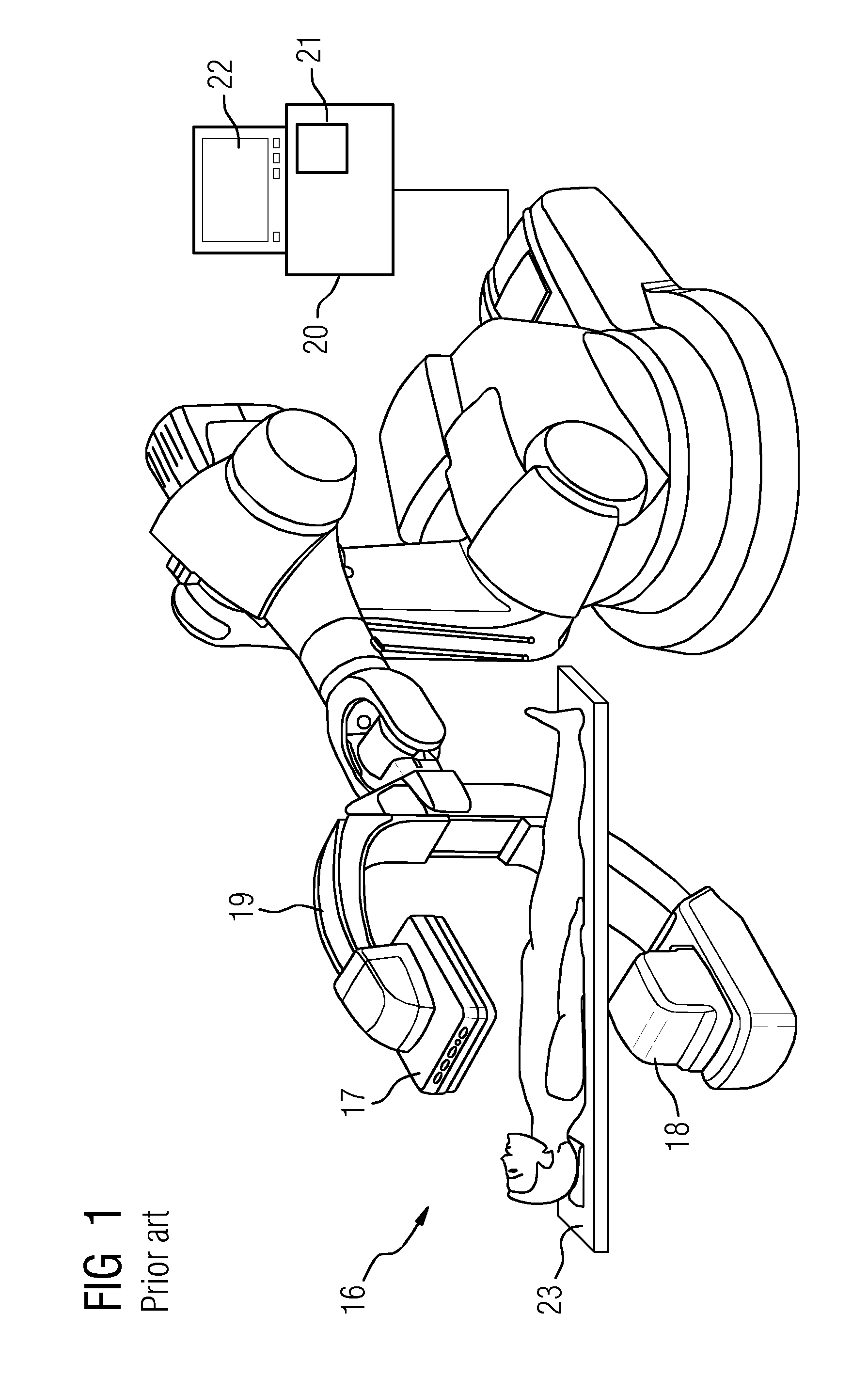
[0001]This application claims the benefit of DE 10 2013 200 021.9, filed on Jan. 2, 2013, which is hereby incorporated by reference in its entirety.BACKGROUND[0002]The present embodiments relate to calibrating a counting digital X-ray detector.[0003]X-ray systems are used for imaging for diagnostic examination purposes and for interventional procedures (e.g., in cardiology, radiology and surgery). X-ray systems 16, as shown in FIG. 1, have an X-ray tube 18 and an X-ray detector 17 (e.g., jointly mounted on a C-arm 19), a high-voltage generator for generating the tube voltage, an imaging system 21 (e.g., including at least one monitor 22), a system control unit 20 and a patient table 23. Biplane systems (e.g., having two C-arms) are likewise employed in interventional radiology. Generally, flat-panel X-ray detectors find application as X-ray detectors in many fields of medical X-ray diagnostics and intervention (e.g., in radiography, interventional radiology, cardioangiography), but ...

Claims


Application Information

Patent Timeline
Patent Type & Authority Patents(United States)
IPC IPC(8): G01T7/00G01T1/24
CPCG01T1/247G01T7/005
Inventor REITZ, SILKESPAHN, MARTIN
Owner SIEMENS HEALTHCARE GMBH
Learn More